SECTION 6
LOW PRESSURE WATER
May 2003
6-6
05148390
6.2.3 Booster Pump
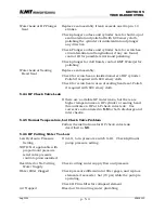
The LP cutting water circuit (refer to Figure 6.2) incorporates several
features relating to the booster pump:
a)
Booster pump overpressure protection—relief valve (3) is built into
the booster pump body and is intended to prevent excessive pump
outlet pressure. This relief valve typically operates when the
intensifier is dead-headed.
b)
If either check valve (13) leaks, the circuit and booster pump could
be subjected to HP water from the intensifier. Inline relief valve
(10)—provides circuit and booster pump protection in the event of
a leaking check valve (13) at the intensifier.
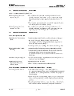
c)
High cutting water supply pressure could result if circulation were
blocked as with dead headed HP water flow. Orifice (7) and check
valve (9) allow a minimal amount of LP water to circulate through
the filter back to the pump inlet, thereby reducing the likelihood of
overheating the cutting water.
d)
If temperature of cutting water at the booster pump outlet is too
high, then temperature switch (2) activates an automatic
shutdown circuit in the PLC that stops the main electric motor
(pumps stop rotating). Note that temperature switch (2) is located
on manifold (18) for Q and later T series KMT Waterjet pumps, but
is located on the booster pump for earlier series pumps (see Detail
A, Figure 6.2)
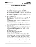
e)
If water pressure to the booster pump inlet is too low, then the
pump might be starved, resulting in pump damage. Pressure
switch (17) activates an automatic shutdown circuit in the PLC
when pressure drops below the switch setting. Logic in the PLC
ignors momentary low pressure signals that might result in
erroneous shutdown commands. Typical conditions likely to cause
low booster pump inlet pressure are clogged LP filter or problems
with the customer-supplied cutting water pressure.
6.2.4 Low Pressure System Protection
The booster pump pressure relief valve (3) is adjusted by turning with a
flat blade screwdriver. Turn clockwise to increase pressure or
counterclockwise to decrease pressure. Some booster pumps have and
exposed adjustment screw, while on others the adjustment screw is
accessed by removing an acorn nut.
Summary of Contents for STREAMLINE SL-IV PLUS
Page 44: ...SECTION 6 LOW PRESSURE WATER May 2003 6 4 05148390 Figure 6 2 LP Cutting Water Supply Circuit ...
Page 78: ...SECTION 7 HIGH PRESSURE WATER May 2003 p 7 30 49831951 ...
Page 82: ...SECTION 8 ELECTRICAL SYSTEM Aug 2002 p 8 4 49836323 ...
Page 111: ...SECTION 12 PARTS LISTS July 2003 page 12 5 49836349 ...
Page 113: ...SECTION 12 PARTS LISTS July 2003 page 12 7 49836349 ...
Page 115: ...SECTION 12 PARTS LISTS July 2003 page 12 9 49836349 ...
Page 117: ...SECTION 12 PARTS LISTS July 2003 page 12 11 49836349 ...
Page 119: ...SECTION 12 PARTS LISTS July 2003 page 12 13 49836349 ...
Page 121: ...SECTION 12 PARTS LISTS July 2003 page 12 15 49836349 ...
Page 123: ...SECTION 12 PARTS LISTS July 2003 page 12 17 49836349 ...
Page 125: ...SECTION 12 PARTS LISTS July 2003 page 12 19 49836349 ...
Page 127: ...SECTION 12 PARTS LISTS July 2003 page 12 21 49836349 ...
Page 129: ...SECTION 12 PARTS LISTS July 2003 page 12 23 49836349 ...
Page 131: ...SECTION 12 PARTS LISTS July 2003 page 12 25 49836349 ...
Page 133: ...SECTION 12 PARTS LISTS July 2003 page 12 27 49836349 ...
Page 135: ...SECTION 12 PARTS LISTS July 2003 page 12 29 49836349 ...
Page 137: ...SECTION 12 PARTS LISTS July 2003 page 12 31 49836349 ...
Page 139: ...SECTION 12 PARTS LISTS July 2003 page 12 33 49836349 ...
Page 141: ...SECTION 12 PARTS LISTS July 2003 page 12 35 49836349 ...
Page 143: ...SECTION 12 PARTS LISTS July 2003 page 12 37 49836349 ...
Page 145: ...SECTION 12 PARTS LISTS July 2003 page 12 39 49836349 ...
Page 146: ......
Page 147: ......


