SECTION 6
LOW PRESSURE WATER
May 2003
6-1
05148390c
Section 6 LOW PRESSURE WATER SYSTEM
6
Low Pressure Water System
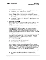
The SL-IV Waterjet Pump is equipped with two low pressure circuits:
•
Cutting water supply for HP intensifier assembly.
•
Cooling water supply for the oil-to-water heat exchanger.
The low pressure water system supplies the pump with the following:
•
Water of sufficient cleanliness and pressure to the inlets of the two (2)
HP cylinders.
•
Cooling water of sufficient flow rate and low temperature to the oil-to-
water heat exchanger.
6.1
Oil Cooling Water Supply
The oil cooling water supply circuit includes the water modulating valve.
Refer to Figure 6.1 for a schematic diagram of the oil cooling water
circuit.
See
“Reciculation System”
Section 10.2 for details on adjustment of
water modulating valve (2).
The maximum flow rate of the cooling water is specified in Section 11
“
Specifications
” under “Hydraulic Oil Cooling.” A minimum inlet
pressure of 40 psig and 70
0
Fahrenheit maximum inlet temperature is
required to maintain oil temperature under extreme operating conditions.
6.2 Cutting
Water
Supply
Refer to Figure 6.2 for a schematic diagram of the LP cutting The cutting
water supply circuit. Refer to the Parts Lists (Section 12) for detailed
component information on the LP cutting water circuit. The LP water
supply includes the following:
•
Low pressure water filter
•
Inlet water shutoff valve (solenoid operated)
•
Booster pump driven by main motor
•
Several pressure gages and switches, and a temperature switch
Most components in the LP cutting water supply circuit are stainless
steel or neoprene or other plastic. A stainless steel inlet solenoid shutoff
valve (11) is available on request. Pressure and temperature switches are
connected to a PLC located in the electrical enclosure. The PLC which
monitors out-of-tolerance conditions, including the following:
•
Low water pressure at the booster pump inlet (switch (17), T and Q
series).
•
Low water pressure at the intensifier inlet (switch (16), T and Q
series).
Summary of Contents for STREAMLINE SL-IV PLUS
Page 44: ...SECTION 6 LOW PRESSURE WATER May 2003 6 4 05148390 Figure 6 2 LP Cutting Water Supply Circuit ...
Page 78: ...SECTION 7 HIGH PRESSURE WATER May 2003 p 7 30 49831951 ...
Page 82: ...SECTION 8 ELECTRICAL SYSTEM Aug 2002 p 8 4 49836323 ...
Page 111: ...SECTION 12 PARTS LISTS July 2003 page 12 5 49836349 ...
Page 113: ...SECTION 12 PARTS LISTS July 2003 page 12 7 49836349 ...
Page 115: ...SECTION 12 PARTS LISTS July 2003 page 12 9 49836349 ...
Page 117: ...SECTION 12 PARTS LISTS July 2003 page 12 11 49836349 ...
Page 119: ...SECTION 12 PARTS LISTS July 2003 page 12 13 49836349 ...
Page 121: ...SECTION 12 PARTS LISTS July 2003 page 12 15 49836349 ...
Page 123: ...SECTION 12 PARTS LISTS July 2003 page 12 17 49836349 ...
Page 125: ...SECTION 12 PARTS LISTS July 2003 page 12 19 49836349 ...
Page 127: ...SECTION 12 PARTS LISTS July 2003 page 12 21 49836349 ...
Page 129: ...SECTION 12 PARTS LISTS July 2003 page 12 23 49836349 ...
Page 131: ...SECTION 12 PARTS LISTS July 2003 page 12 25 49836349 ...
Page 133: ...SECTION 12 PARTS LISTS July 2003 page 12 27 49836349 ...
Page 135: ...SECTION 12 PARTS LISTS July 2003 page 12 29 49836349 ...
Page 137: ...SECTION 12 PARTS LISTS July 2003 page 12 31 49836349 ...
Page 139: ...SECTION 12 PARTS LISTS July 2003 page 12 33 49836349 ...
Page 141: ...SECTION 12 PARTS LISTS July 2003 page 12 35 49836349 ...
Page 143: ...SECTION 12 PARTS LISTS July 2003 page 12 37 49836349 ...
Page 145: ...SECTION 12 PARTS LISTS July 2003 page 12 39 49836349 ...
Page 146: ......
Page 147: ......


