


A:
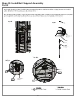
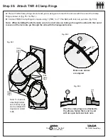
Place (451) Bell Top on top of (452) Bell Support so the angled and back edges are flush then attach with 3
(S20) #8 x 1-3/8” Wood Screws. Repeat by attaching (453) Bell Top Right to top of (452) Bell Support. Rounded
ends of (451) Bell Top and (453) Bell Top RT are at the bottom. (fig. 45.1 & 45.2)
B:
Centred above the door on (063) Narrow Front Panel place each Bell Support Assembly so they are tight and
form a peak then attach to (023) Narrow Front Panel with 1 (S3) #8 x 2-1/2” Wood Screw and 1 (S11) #8 x 2”
Wood Screw per assembly. (fig. 45.3)
Step 45: Install Bell Support Assembly
Part 1
Hardware
Wood Parts
Fig. 45.1
Fig. 45.3
Fig. 45.2
Top View
S20
S20
2 x
#8 x 2” Wood Screw
6 x
#8 x 1-3/8” Wood Screw
2 x
#8 x 2-1/2” Wood Screw
S11
1 x
Bell Top 5/8 x 3-3/8 x 11-1/4”
1 x
Bell Top RT 5/8 x 3-3/8 x 11-1/4”
2 x
Bell Support 1-1/2 x 1-1/2 x 10-5/8”
451
453
452
S20
S3
451
Flush
453
452
Front of assembly
Back of assembly
(next to fort)
063
S11
S3
S3
86
Summary of Contents for Cedar Summit COPPER RIDGE PLAYSET
Page 111: ...NOTES ...