Component Descriptions
06-237518-001
2-9
July 2018
2-3.7
Pilot Line Bleed Valve
Install a Pilot Line Bleed Valve (P/N 38-400007-001) in the unused actuation hose connection
in the last cylinder of a cylinder bank. The end-of-line leak/vent valve prevents a possible grad-
ual pressure build-up in the pilot line should the solenoid release unit develop a leak, thus pre-
venting an unintended system discharge.
Figure 2-12. Pilot Line Bleed Valve (P/N 38-400007-001)
Note:
For LPCB Approved systems, please use the alternative Pilot Line Bleed Valve Kit, P/N:
01-3388-1000.
This kit of parts includes: Pilot Line Bleed Valve (Part # 01-3388-0000) and the neces-
sary adaptor(s) for connection to the Quick Connect fittings on the Kidde IGS - 400 Se-
ries Valve.
2-3.8
Quick Connect Cables
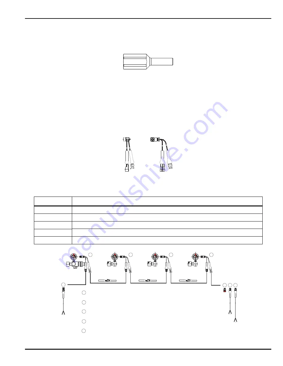
Quick Connect cables provide a fast method of wiring the pressure gauges of the Release Unit
and Slave Cylinder Gauge Assemblies.
Figure 2-13. Quick Connect Cables
Figure 2-14. Quick Connect Cabling Example
Table 2-7. Kidde IGS Quick Connect Cable Part Numbers
Part Number
Description
38-400005-100 L Plug x 2 Cable, Dual Core (0.34mm x 300mm) x Quick Connects (Male & Female)
38-400005-101 Gauge Signal Line - Quick Connect Terminal Plug (MALE)
38-400005-102 Gauge Signal Line - Quick Connect (MALE) Connector with 3m Fly lead (Dual Core Cable)
38-400005-103 Quick Connect (Male) x Dual Core (0.34mm x 1000mm) Fly-Lead
38-400005-105 Quick Connect (Female) x Dual Core (0.34mm x 1000mm) Fly-Lead
KIDDE
WP XXX BAR
38-40000X-00X
MM/YYYY UK
psi
bar
XX
/X
X
Overcharged
Recharge
(-4°F )
-20°C
F
I
S
U
R
O
E W
N
H
T
I E T
R
N
O
S
A
G
Y
L
VdS
0
50
100
250
300
500
0
450 0
4000
315
25 00
1000
1500
2000
150
350 0
3000
200
(70°F )
21°C
(122°F)
50°C
Manuf. for
15-8025-1200
WIKA
PGS21.050
0786/09
FA
-N
o.
xxx
xx
xx
CL1.6
KIDDE
WP 240 BAR
38-400005-002
MM/YYYY UK
psi
bar
XX
/X
X
Overcharged
Rech arge
(-4°F)
-20°C
F
I
S
U
R
O
E W
N
H
T
I E T
R
N
O
S
A
G
Y
L
VdS
0
50
100
250
300
500
0
45 00
4000
315
2 500
1000
150 0
2000
150
35 00
3000
200
(70°F)
21°C
(122°F)
50°C
Manuf. for
15-8025-1200
WIKA
PGS21.050
0786/09
FA
-N
o.
xxx
xx
xx
CL1.6
KIDDE
WP 240 BAR
38-400005-002
MM/YYYY UK
psi
bar
XX
/X
X
Overcharg ed
Recharge
(-4°F)
-20°C
F
I
S
U
R
O
E W
N
H
T
I E T
R
N
O
S
A
G
Y
L
VdS
0
50
100
250
300
50 0
0
4 500
4000
31 5
2500
1000
15 00
2000
150
3 500
3000
200
(70°F)
21°C
(122°F )
50°C
Man uf. for
15-8025-1200
WIKA
PGS21.050
0786/09
FA
-N
o.
xxx
xx
xx
CL1.6
psi
bar
XX
/X
X
Overcharged
Recharge
(-4°F )
-20°C
F
I
S
U
R
O
E W
N
H
T
I E T
R
N
O
S
A
G
Y
L
VdS
0
50
100
250
300
500
0
45 00
4000
315
25 00
1000
150 0
2000
150
350 0
3000
200
(70°F )
21°C
(122°F)
50°C
Manuf. for
15-8025-1200
WIKA
PGS21.050
0786/09
FA
-N
o.
xxx
xx
xx
CL1.6
1
3
4
5
1
Female Quick Connector - 1m Long "Fly-Lead" (2 Core Cable)
Part #: 38-400005-105
-
For Connection to Panel/Junction Box
2
Standard Male/Female Quick Conection Gauge Signal Plug (PG7 Gland) -
x2 300mm Long 2 Core Cables. Part #: 38-400005-100
3
Quick Connect
Termination
Plug (Male)
P
art #: 38-400005-10
1 - For Ingress protection if EOL Circuit is not required.
4
Male Quick Connector -
3
m Long "Fly-Lead" (2 Core Cable)
Part #: 38-400005-10
2 - Back to Junction Box for Class A wiring
5
Male Quick Connect
or - 1m Long "Fly-Lead" (2 Core Cable)
Part #: 38-400005-10
3 - Back to Junction Box for Class A wiring
2
2
2
2
F
M
F
M
F
M
F
M
F
M
Summary of Contents for 400 Series
Page 2: ...Table i Revision History Revision Change Description AA Initial Release ...
Page 16: ...July 2018 xiv 06 237518 001 THIS PAGE INTENTIONALLY LEFT BLANK ...
Page 157: ...06 237518 001 A 1 July 2018 APPENDIX A SAFETY DATA SHEETS ...
Page 188: ...July 2018 A 2 06 237518 001 THIS PAGE INTENTIONALLY LEFT BLANK ...
Page 189: ......


