background image

78

6000 X-Series Oscilloscopes Service Guide 

4

Troubleshooting


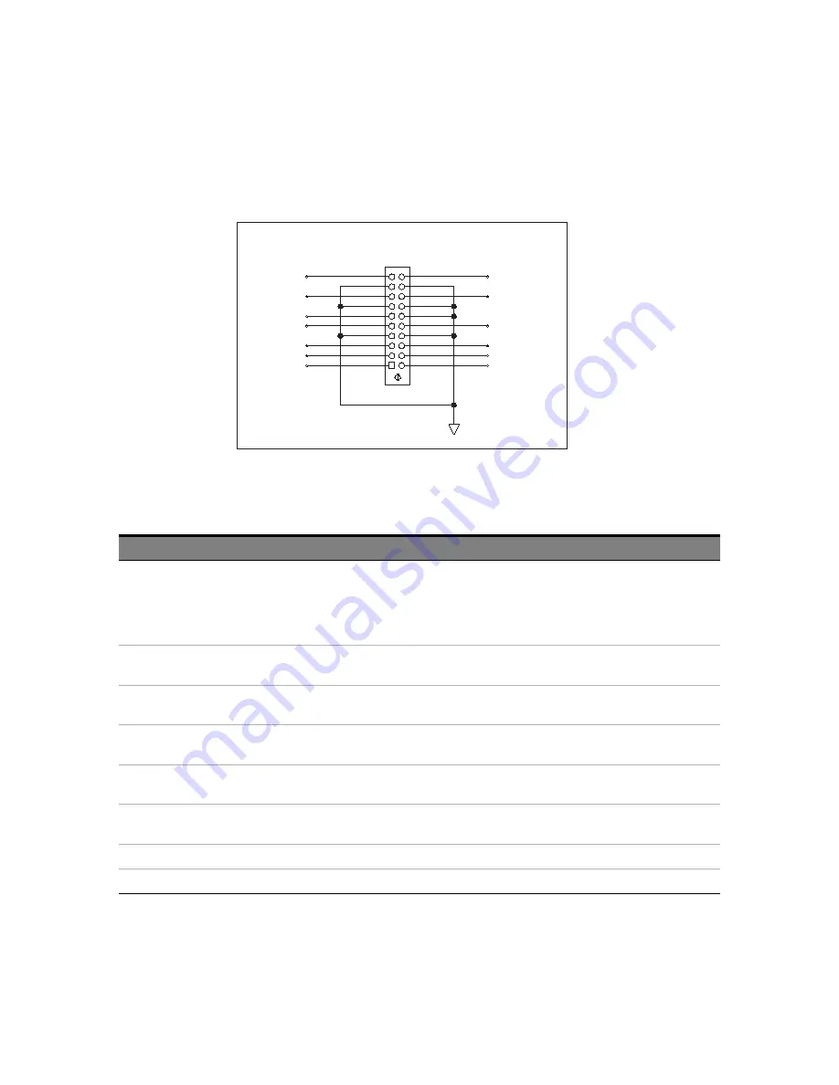
Figure 16

J105 connector pinout

VP2V5

VP5V

VP1V8

VM13V

VP3V3

VP3V3

VP13VF

GND

VP1V8

J105

16

13

14

17

4

8

19

15

9

6

11

20

12

3

18

1

2

5

10

7

VP2V5

VM6V5

VP5V

VP1V3

VP1V3

Power Cable Header

Table 21

Power supplies to acquisition board (from power board J105)

Supply

Test Point

Expected Value

If Good

If Bad

VP13VF

J105, pin 20

+12.9V to +13V, 

>+12.8 V when loaded 

by acquisition board, 

see also 

“VP13VF"

on 

page 79

Supply is good.

Replace the power board.

VP5V

J105, pin 8

J105, pin 18

+5.051 V ±3%

Supply is good.

Replace the power board.

VP3V3

J105, pin 3

J105, pin 13

+3.353 V ±3%

Supply is good.

Replace the power board.

VP2V5

J105, pin 5

J105, pin 15

+2.508 V ±1.6%

Supply is good.

Replace the power board.

VP1V8

J105, pin 1

J105, pin 11

+1.825 V ±2.6%

Supply is good.

Replace the power board.

VP1V3

J105, pin 2

J105, pin 12

+1.3 V ±3%

Supply is good.

Replace the power board.

VM13V

J105, pin 10

-13 V ±2%

Supply is good.

Replace the power board.

VM6V5

J105, pin 6

-6.5 V ±2.2%

Supply is good.

Replace the power board.

Summary of Contents for InfiniiVision 6000 X Series

Page 1: ...Keysight InfiniiVision 6000 X Series Oscilloscopes Service Guide...

Page 2: ...f which can be found at www keysight com find sweula The license set forth in the EULA represents the exclusive authority by which the U S government may use modify distribute or disclose the Software...

Page 3: ...librating and Adjusting This chapter explains how to adjust the oscilloscope for optimum operating performance 4 Troubleshooting This chapter begins with suggestions for solving general problems that...

Page 4: ...applies only to Mixed Signal Oscilloscope MSO models or DSO models that have been upgraded to an MSO Abbreviated instructions for pressing a series of keys Instructions for pressing a series of keys...

Page 5: ...tegory 14 Measurement Category Definitions 14 Maximum Input Voltages 15 Environmental Conditions 16 Specifications 16 Contact us 16 2 Testing Performance Overview 18 List of Test Equipment 19 Conventi...

Page 6: ...Performance Test Record 52 3 Calibrating and Adjusting User Calibration 57 To perform User Calibration 57 User Calibration Status 57 4 Troubleshooting Solving General Problems with the Oscilloscope 6...

Page 7: ...power to the acquisition board 77 To check power to the front panel AutoProbe interfaces 80 5 Replacing Assemblies To remove the cabinet 85 To remove the rear deck assembly 86 To remove the power supp...

Page 8: ...vice Guide Contents 6 Replaceable Parts Ordering Replaceable Parts 116 Listed Parts 116 Unlisted Parts 116 Direct Mail Order System 116 Exchange Assemblies 117 Exploded Views 118 Replaceable Parts Lis...

Page 9: ...gure 10 Default setup screen 66 Figure 11 Example pulses 68 Figure 12 Verify line filter AC output 72 Figure 13 Verify power supply DC output 74 Figure 14 Location of the J104 fan connector 75 Figure...

Page 10: ...splay assembly removed 103 Figure 37 Disconnecting the softkey board cable 104 Figure 38 Disconnecting the speaker microphone cable 105 Figure 39 Removing the keyboard 106 Figure 40 Keyboard and keypa...

Page 11: ...cy 35 Table 11 Bandwidth 3 dB Test Limits 38 Table 12 Equipment Required to Verify Bandwidth 3 dB 38 Table 13 Equipment Required to Verify Time Base Accuracy 43 Table 14 Internal Trigger SensitivityTe...

Page 12: ...12 6000 X Series Oscilloscopes Service Guide Tables...

Page 13: ...ntains a partial list of characteristics and specifications for the Keysight InfiniiVision 6000 X Series oscilloscopes For a full list of Keysight InfiniiVision 6000 X Series oscilloscopes characteris...

Page 14: ...performed on circuits directly connected to the low voltage installation Examples are measurements on household appliances portable tools and similar equipment Measurement category III is for measurem...

Page 15: ...5 Vrms is detected However the inputs could still be damaged depending on the time constant of the signal The 50 input protection functions only when the oscilloscope is powered on The maximum input v...

Page 16: ...operating altitude 3 962 m 13 000 ft Overvoltage Category This product is intended to be powered by MAINS that comply to Overvoltage Category II which is typical of cord and plug connected equipment...

Page 17: ...ify digital channel threshold accuracy MSO models only 24 To verify DC vertical gain accuracy 29 To verify dual cursor accuracy 34 To verify bandwidth 3 dB 38 To verify time base accuracy 43 To verify...

Page 18: ...for you to connect the oscilloscope probes to function generators and measurement equipment Let the Equipment Warm Up Before Testing For accurate test results let the test equipment and the oscillosco...

Page 19: ...sight E9304A or N8482A 50 BNC Cable qty 3 BNC BNC 48 length Keysight 8120 1840 Cable Type N m 609 6 mm 24 in Keysight 11500B Probe cable No substitute 16 chanel Keysight N6450 60001 or N2756 60001 8 c...

Page 20: ...The following conventions will be used when referring to oscilloscope models throughout this chapter Table 2 Conventions DSO X 6002A DSO X 6004A MSO X 6002A MSO X 6004A Bandwidth Option Referred to a...

Page 21: ...ne side of the Berg strip solder a jumper wire to all of the pins shown in Figure 1 on page 22 3 On the other side of the Berg strip solder another jumper wire to all of the pins 4 Solder the center o...

Page 22: ...Oscilloscopes Service Guide 2 Testing Performance Figure 1 Constructing the 8 by 2 Connector Jumper 2 Signal Lead from scope s MSO cable 8 x 2 Berg Strip BNC Panel Mount Connector Ground Lead from sc...

Page 23: ...connect digital channels D0 D1 D2 and D3 to the Probe Comp signal on the center of the front panel 3 Press the AutoScale key If four square waves appear the acquisition system is functioning correctl...

Page 24: ...When to Test You should perform this test every two years or after 4000 hours of operation whichever comes first What to Test Use these instructions to test the threshold settings of digital channels...

Page 25: ...C cable assembly to connect digital channels D0 D7 to one side of the BNC Tee Then connect the D0 D7 ground lead to the ground side of the 8 by 2 connector See Figure 2 Table 4 Equipment Required to T...

Page 26: ...de of the BNC Tee 5 Connect the BNC Tee to the Channel 1 output of the precision source as shown in Figure 2 6 On the oscilloscope press the Digital key then press the Thresholds softkey then press th...

Page 27: ...ce to decrease the offset voltage in increments of 10 mV until the activity indicators for digital channels D7 D0 are all at digital low levels Record the precision source voltage in the Performance T...

Page 28: ...output of the precision source Then connect the D15 D8 ground lead to the ground side of the 8 by 2 connector 10 Repeat this procedure steps 6 through 8 for digital channels D15 D8 to verify threshold...

Page 29: ...full scale Full scale is defined as 16 mV on the 1 mV div range Full scale on all other ranges is defined as 8 divisions times the V div setting Table 7 Equipment Required to Verify DC Vertical Gain...

Page 30: ...Table 8 Settings Used to Verify DC Vertical Gain Accuracy Volts Div Setting Precision Source Setting Test Limits 5 V Div 35 V 34 V to 36 V 2 V Div 14 V 13 6 V to 14 4 V 1 V Div 7 V 6 8 V to 7 2 V 500...

Page 31: ...ype then turn the Entry knob to select Average Full Screen and press Add Measurement 4 Read the current average voltage value as V1 5 Use the BNC tee and cables to connect the precision source power s...

Page 32: ...multimeter reading displays the first Volts div precision source setting value in Table 8 depending on the oscilloscope model 7 Disconnect the multimeter 8 Wait until the measurement settles 9 Read th...

Page 33: ...le 8 depending on the oscilloscope model 13 Finally repeat this procedure for the remaining channels to be tested Use a Blocking Capacitor to Reduce Noise On the more sensitive ranges such as 1 mV div...

Page 34: ...cilloscope a Set the Volts Div setting to the value in the first line in Table 10 depending on the oscilloscope model b Adjust the channel 1 position knob to place the baseline at 0 5 major division f...

Page 35: ...Settings Used to Verify Dual Cursor Accuracy Volts Div Setting Precision Source Setting Test Limits 5 V Div 35 V 33 832 V to 36 168 V 2 V Div 14 V 13 533 V to 14 467 V 1 V Div 7 V 6 766 V to 7 234 V 5...

Page 36: ...urrent from the Precision Source ground to the DUT ground Figure 5 Setting up Equipment for Dual Cursor Accuracy Test 5 Adjust the output so that the multimeter reading displays the first Volts div pr...

Page 37: ...y with the remaining Volts div setting values in Table 10 11 Finally repeat this procedure for the remaining channels to be tested Use a Blocking Capacitor to Reduce Noise On the more sensitive ranges...

Page 38: ...Bandwidth 3 dB Test Limits Models Test Limits 6 GHz Models All channels 3 dB dc to 6 GHz 4 GHz Models All channels 3 dB dc to 4 GHz 2 5 GHz Models All channels 3 dB dc to 2 5 GHz 1 GHz Models All cha...

Page 39: ...Guide 39 Figure 7 Setting Up Equipment for Bandwidth 3 dB Verification Test 2 Set up the power meter Set the power meter to display measurements in units of watts Power Splitter Power Sensor Signal Ge...

Page 40: ...measurement a Press the Meas key b Press the Clear Meas softkey and then the Clear All softkey c Press the Type softkey and use the Entry knob to select AC RMS Full Screen Std Deviation within the se...

Page 41: ...Models 100 ps div 2 5 GHz Models 100 ps div 1 GHz Models 500 ps div 12 Note the oscilloscope AC RMS FS 1 reading at the bottom of the screen 13 Note the reading on the power meter and covert to Vrms u...

Page 42: ...ve the power splitter from the channel 1 to the channel 2 input 17 Turn off the current channel and turn on the next channel using the channel keys 18 Repeat steps 3 through 17 for the remaining chann...

Page 43: ...y to 200 mv div c Set the oscilloscope horizontal sweep speed control to 5 ns div d Adjust the intensity to get a sharp clear trace e Turn off Jitter Free Trigger press Utility Options Preferences Jit...

Page 44: ...m where the rising edge crosses the center horizontal grid line to the center vertical grid line Each ns equals 0 1 ppm of time base error Time base accuracy limit 1 6 ppm aging Aging factors 1 year 0...

Page 45: ...ll triggered Table 14 Internal Trigger SensitivityTest Limits BW Models V div Frequency Sensitivity 1 GHz 10 mV div All greater of 1 div or 5 mVpp 10 mV div All 0 6 div 2 5 GHz 4 GHz and 6 GHz 10 mV d...

Page 46: ...vity Equipment Critical Specifications Recommended Model Part Signal Generator 100 kHz to 6 GHz sine waves Keysight N5171B with 6 GHz option Power splitter Outputs differ 0 20 dB Keysight 11667A Power...

Page 47: ...Connect the equipment see Figure 8 a Connect the signal generator output to the oscilloscope channel 1 input Figure 8 Setting Up Equipment for Internal Trigger Sensitivity Test b Set channel 1 Impeda...

Page 48: ...asses If adjusting the trigger does not help change the trigger edge to trigger on falling edge try adjusting the trigger level again If trigger on falling edge makes the trigger stable the test still...

Page 49: ...nnect the equipment see Figure 9 a Use the N cable to connect the signal generator to the power splitter input b Connect one output of the power splitter to the Aux Trig input through a 50 feedthrough...

Page 50: ...s Service Guide 2 Testing Performance Figure 9 Setting Up Equipment for 4 Channel External Trigger Sensitivity Test Power Splitter Power Sensor Signal Generator Oscilloscope Power Meter N Cable N to B...

Page 51: ...ey then press the Source softkey to set the trigger source to External 7 Check for stable triggering and adjust the trigger level if necessary Triggering is indicated by the Trig d indicator at the to...

Page 52: ...cy Range Power Supply Setting Test Limits Channel 1 Channel 2 Channel 3 Channel 4 5 V Div 35 V 34 V to 36 V ________ ________ ________ ________ 2 V Div 14 V 13 6 V to 14 4 V ________ ________ ________...

Page 53: ...________ ________ ________ 20 mV Div 140 mV 135 33 mV to 144 67 mV ________ ________ ________ ________ 10 mV Div 70 mV 67 66 mV to 72 34 mV ________ ________ ________ ________ 5 mV Div 35 mV 33 83 mV...

Page 54: ...___ 2 GHz 10 mV div greater of 1 div or 5 mVpp ________ ________ ________ _______ 10 mV div 0 6 div ________ ________ ________ _______ 1 GHz models 1 GHz 10 mV div greater of 1 div or 5 mVpp ________...

Page 55: ...ions Every two years or after 4000 hours of operation If the ambient temperature is 10 C from the calibration temperature If you want to maximize the measurement accuracy The amount of use environment...

Page 56: ...Otherwise damage to the oscilloscope can occur CAUTION USE EXTERNAL FAN TO REDUCE TEMPERATURE When you must operate the oscilloscope with its cover and main shield removed use an external fan to prov...

Page 57: ...nvalidate your Certificate of Calibration If NIST National Institute of Standards and Technology traceability is required perform the procedures in Chapter 2 in this book using traceable sources To pe...

Page 58: ...58 6000 X Series Oscilloscopes Service Guide 3 Calibrating and Adjusting...

Page 59: ...If you cannot see a channel Next this chapter describes procedures for Verifying Basic Operation of the oscilloscope To power on the oscilloscope To perform hardware self test To perform front panel...

Page 60: ...Parts starting on page 115 If there is no display Check that the power cord is firmly seated in the oscilloscope power receptacle Check that the power source is live Check that the front panel power s...

Page 61: ...nts each probe s individual ground lead should also be connected to a ground point closest to the signal point in the circuit under test Check that the trigger setup is correct A correct trigger setup...

Page 62: ...rm the remaining checks in this topic to make sure the oscilloscope channels are on and to obtain an automatic setup Check that the desired oscilloscope channels are turned on a Press the analog chann...

Page 63: ...page 115 The power cord provided is matched to the country of origin Press the power switch When the oscilloscope is turned on the front panel LEDs will briefly light up in groups from bottom to top N...

Page 64: ...ovide an 80 confidence level that the oscilloscope is operating properly To perform front panel self test Pressing Utility Service Front Panel Self Test lets you test the front panel keys and knobs as...

Page 65: ...position probe factor to 1 0 if an AutoProbe probe is not connected to the channel Trigger Edge trigger Auto sweep mode 0 V level channel 1 source dc coupling rising edge slope 40 ns holdoff time Dis...

Page 66: ...oard To perform an Auto Scale on the Probe Comp signal 1 Press the Default Setup key The oscilloscope is now configured to its default settings 2 Connect an oscilloscope probe from channel 1 to the Pr...

Page 67: ...wered on and the probe is connected securely to the front panel analog channel input BNC and to the Demo 2 Probe Comp terminal 6 If you still do not see the waveform use the troubleshooting flowchart...

Page 68: ...63 90 probes the trimmer capacitor is the yellow adjustment on the probe tip On other probes the trimmer capacitor is located on the probe BNC connector Figure 11 Example pulses 5 Connect probes to al...

Page 69: ...Required to Troubleshoot the Oscilloscope Equipment Critical Specifications Recommended Model Part Digital multimeter Accuracy 0 05 1 mV resolution Keysight 34401A 34461A Oscilloscope Capable of meas...

Page 70: ...oscope on a properly grounded ESD mat and wear a properly grounded ESD strap CAUTION MAKE SURE EARTH GROUND IS MAINTAINED FOR THE FRONT DECK If separating the front and rear decks for example to check...

Page 71: ...ed overview of troubleshooting power to the oscilloscope s internal assemblies Start 13V Supply Voltage Okay Yes No Power Supply AC Input Okay No End No Replace Power Supply Replace Power Board No Rep...

Page 72: ...mbly troubleshooting on page 69 2 Connect the power cord and turn on the oscilloscope 3 Verify that AC power is present on LINE brown wire and NEUTRAL blue wire at SK1 on the power supply using a DVM...

Page 73: ...AC input is good 1 Follow the instructions in To prepare for internal assembly troubleshooting on page 69 2 Connect the negative lead of the multimeter to a ground point on the oscilloscope 3 Connect...

Page 74: ...C output J102 8 10 3 5 Table 19 DC output from power supply Supply Test Point Expected Value If Good If Bad VP13V Connector J102 pins 8 9 10 13V pins 3 4 5 GND 13 V 0 2V Indicates power supply is good...

Page 75: ...e acquisition board If the fan is not running it may be defective First verify the fan power using these steps 1 Follow the instructions in To prepare for internal assembly troubleshooting on page 69...

Page 76: ...able If the voltage measured is out of range replace the power supply If 12V is present but the fan is not spinning the problem is either the fan or the FAN_PWM_DRIVE control from the acquisition boar...

Page 77: ...the instructions in To prepare for internal assembly troubleshooting on page 69 2 Connect the negative lead of the multimeter to a ground point on the oscilloscope 3 Connect the power cord and turn on...

Page 78: ...aded by acquisition board see also VP13VF on page 79 Supply is good Replace the power board VP5V J105 pin 8 J105 pin 18 5 051 V 3 Supply is good Replace the power board VP3V3 J105 pin 3 J105 pin 13 3...

Page 79: ...loscope 2 Disconnect the power cord 3 Disconnect cable assembly from the power board s J105 connector 4 Connect the power cord and turn on the oscilloscope 5 Using a DMM in DC volts mode measure VP13V...

Page 80: ...bad assemblies 1 Follow the instructions in To prepare for internal assembly troubleshooting on page 69 2 Connect the negative lead of the multimeter to a ground point on the oscilloscope 3 Connect t...

Page 81: ...r board J106 Supply Test Point Expected Value If Good If Bad VP13VF_PRB J106 pin 1 13 V 2 Supply is good Replace the power board VM13VF_PRB J106 pin 2 13 V 2 Supply is good Replace the power board VM6...

Page 82: ...82 6000 X Series Oscilloscopes Service Guide 4 Troubleshooting...

Page 83: ...ve the cabinet 85 To remove the rear deck assembly 86 To replace the battery 94 To remove the acquisition board 95 To remove the front panel knobs 99 To remove the front bezel assembly 100 To remove t...

Page 84: ...ce Whenever possible perform the procedures with the power cord removed from the oscilloscope WARNING AVOID ELECTRICAL SHOCK Hazardous voltages exist on the LCD assembly and power supply To avoid elec...

Page 85: ...abinet allows access to the rear deck fan assembly power supply cover power supply assembly and power switch assembly 1 Using a TORX T20 driver remove the five screws securing the cabinet to the rear...

Page 86: ...e Guide 5 Replacing Assemblies To remove the rear deck assembly Removing the rear deck allows access to the front deck and acquisition board 1 Remove the BNC securing nuts and washers Figure 19 Removi...

Page 87: ...semblies 5 6000 X Series Oscilloscopes Service Guide 87 2 Using a TORX T10 driver locate and remove all the perimeter screws securing rear deck to front deck Figure 20 Removing perimeter screws securi...

Page 88: ...3 Locate and remove all rear facing screws securing rear deck to front deck You need to remove the AC input shield see To remove the AC input shield on page 93 before you can remove the screw on the l...

Page 89: ...Oscilloscopes Service Guide 89 4 Disconnect the acquisition board control cable the acquisition board power cable and the probe power cable Note cable locations for re assembly Figure 22 Removing cab...

Page 90: ...de 5 Replacing Assemblies 5 Carefully separate rear deck from front deck Take care not damage extender switch WARNING Sheet metal parts may have sharp edges Handle with care to avoid injury Figure 23...

Page 91: ...remove using a TORX T10 driver the two screws securing the shield to the rear deck 2 Once the screws have been removed carefully remove the power supply cover by lifting the cover up and off retainin...

Page 92: ...d remove using a TORX T10 driver the one screw securing the shield to the rear deck 2 Once the screw has been removed carefully remove the probe power shield by lifting the cover up and off retaining...

Page 93: ...te and remove using a TORX T10 driver the two screws securing the shield to the rear deck 2 Once the screws have been removed carefully remove the shield by lifting it up and off retaining tabs on rea...

Page 94: ...eries Oscilloscopes Service Guide 5 Replacing Assemblies To replace the battery If the battery needs to be replaced use a CR2032 1HG or CR2032 HGN 3V manganese dioxide lithium battery Figure 27 Batter...

Page 95: ...Guide 95 To remove the acquisition board These steps show how to remove the acquisition board 1 Using a TORK T6 driver locate and remove the 4 screws on the front of the instrument 4 Channel version F...

Page 96: ...mblies 2 Disconnect display power display video and keyboard cables Note locations for re connection The keyboard cable connector has a latch that must be flipped up before you can disconnect the cabl...

Page 97: ...Replacing Assemblies 5 6000 X Series Oscilloscopes Service Guide 97 3 Using a TORX T10 driver locate and remove 12 mounting screws Figure 30 Acquisition board TORX T10 mounting screw locations...

Page 98: ...98 6000 X Series Oscilloscopes Service Guide 5 Replacing Assemblies 4 Carefully lift acquisition board off front deck Figure 31 Lifting acquisition board off the front deck...

Page 99: ...ce Guide 99 To remove the front panel knobs The front panel knobs must be removed prior to localized front panel overlay installation or front panel disassembly 1 Gently pull on the front panel knobs...

Page 100: ...Remove the bezel from the front deck The bezel is secured to front deck by molded in retaining clips located around the perimeter of the bezel Gently pry these outward either by hand or using a flat h...

Page 101: ...placing Assemblies 5 6000 X Series Oscilloscopes Service Guide 101 2 Before separating the bezel from the front deck unlatch and disconnect the keyboard cable Figure 34 Disconnecting the keyboard cabl...

Page 102: ...scilloscopes Service Guide 5 Replacing Assemblies To remove the display assembly 1 Using a TORX T10 driver remove the two screws that secure the display assembly to the front deck Figure 35 Removing t...

Page 103: ...Replacing Assemblies 5 6000 X Series Oscilloscopes Service Guide 103 2 Take care while guiding display cables through front deck sheet metal openings Figure 36 Display assembly removed...

Page 104: ...5 Replacing Assemblies To remove the keyboard and keypad 1 Remove the softkey board cable from the keyboard board Slide the connector clamp toward the softkey board then slide the ribbon cable out Fi...

Page 105: ...Replacing Assemblies 5 6000 X Series Oscilloscopes Service Guide 105 2 Remove the speaker microphone cable from the keyboard board Figure 38 Disconnecting the speaker microphone cable...

Page 106: ...Oscilloscopes Service Guide 5 Replacing Assemblies 3 To separate the keyboard board from the bezel carefully pull back locking tabs that secure it Figure 39 Removing the keyboard Figure 40 Keyboard a...

Page 107: ...X Series Oscilloscopes Service Guide 107 4 To separate the softkey board from the bezel carefully pull back locking tabs that secure it Figure 41 Unclip the softkey board from the bezel Figure 42 Soft...

Page 108: ...000 X Series Oscilloscopes Service Guide 5 Replacing Assemblies To remove the fan assembly 1 Ensure that the fan power cable has been disconnected from the power board Figure 43 Disconnecting the fan...

Page 109: ...fully slide fan assembly fan and fan mount to the right then lift away from rear deck Note fan mount is soft and can be damaged by sharp sheet metal edges Take care that the fan power cable is not dam...

Page 110: ...00 X Series Oscilloscopes Service Guide 5 Replacing Assemblies To remove the power supply 1 Disconnect all cables between the power supply and the power board Figure 45 Removing cables to from power s...

Page 111: ...g Assemblies 5 6000 X Series Oscilloscopes Service Guide 111 2 Locate and remove using a TORX T10 driver the four screws securing the power supply assembly to the rear deck Figure 46 Removing the powe...

Page 112: ...112 6000 X Series Oscilloscopes Service Guide 5 Replacing Assemblies To remove the power board 1 Disconnect the ground wire from its chassis terminal Figure 47 Disconnecting the ground wire...

Page 113: ...de 113 2 Locate and remove using a TORX T10 driver the four screws securing the power board to the rear deck 3 Slide assembly back and lift out of rear deck 4 Take care that you do not damage the swit...

Page 114: ...s Service Guide 5 Replacing Assemblies 5 To remove the switch extender gently pry open the extender using a flat head screwdriver CAUTION Twisting the latch too much could cause it to break Figure 49...

Page 115: ...ts This chapter describes how to order replaceable assemblies and parts for the Keysight 6000 X Series oscilloscopes Diagrams and parts lists are included for assemblies and hardware that you can orde...

Page 116: ...Order System Within the USA Keysight Technologies can supply parts through a direct mail order system There are several advantages to this system Direct ordering and shipping from the Keysight Technol...

Page 117: ...n that of a new part The exchange parts have a part number in the form XXXXX 695XX After receiving the repaired exchange part from Keysight Technologies a United States customer has 30 days to return...

Page 118: ...ion of the oscilloscope at the time this manual was released Not all parts are shown Your parts may be slightly different than those shown These views provide reference designator numbers that map to...

Page 119: ...Replaceable Parts 6 6000 X Series Oscilloscopes Service Guide 119 Figure 51 Exploded View 2 of 2 MP12 A4 MP14 MP19 MP15 MP18 A3 MP17 MP13 MP16...

Page 120: ...66601 1 Acquisition board 6000 X Series 4 Ch A1 54609 69501 1 Acquisition board 6000 X Series 4 Ch exchange A1 54609 69501 DEF 1 Acquisition board 6000 X Series 4 Ch return A2 54608 66421 1 PCA 2 Chan...

Page 121: ...G Carbon Steel Zn clear Chromate MP1 54608 94303 1 ID Label MSO X 6002A MP1 54609 94303 1 ID Label MSO X 6004A MP1 54608 94305 1 ID Label DSO X 6002A MP1 54609 94305 1 ID Label DSO X 6004A MP2 54608 9...

Page 122: ...0102 1 Rear Deck MP13 54609 00602 1 Shield Power Supply MP14 54609 00604 1 Shield AC Input MP15 54609 00606 1 Shield Probe Power MP16 54609 44701 1 Fan Mount MP17 3160 4377 1 Fan MP18 54695 43901 1 Ex...

Page 123: ...Display Backlight Touch Not shown 54609 61607 1 Cable Power Supply Sense Not shown 54609 61610 1 LVDS Display Cable Not shown 54709 61610 1 Soft Keyboard Cable Not shown 75019 61604 1 Cable Ground Wir...

Page 124: ...panish 4 channel Not shown 54608 94316 Overlay Spanish 2 channel Not shown 54609 94313 Overlay German 4 channel Not shown 54608 94313 Overlay German 2 channel Not shown 54609 94318 Overlay Portuguese...

Page 125: ...any manner not specified by the manufacturer The protective features of this product may be impaired if it is used in a manner not specified in the operation instructions Before Applying Power Verify...

Page 126: ...maintained In Case of Damage Instruments that appear damaged or defective should be made inoperative and secured against unintended operation until they can be repaired by qualified service personnel...

Page 127: ...ductor on permanently installed equipment L Line conductor on permanently installed equipment On mains supply Off mains supply Standby mains supply The instrument is not completely disconnected from t...

Page 128: ...isk of electric shock Do not apply around or remove from HAZARDOUS LIVE conductors Application around and removal from HAZARDOUS LIVE conductors is permitted Caution hot surface Ionizing radiation CAT...

Page 129: ...118 removal 86 front panel self test 64 H hardware self test 64 I internal self tests 64 K keyboard removal 95 Keysight contact information 16 L LED startup sequence 63 lid removal 85 line filter boa...

Page 130: ...57 storage lid removal 85 T test connector constructing 21 digital channels 23 equipment 19 record 52 threshold accuracy digital channel 24 test diagram 26 trace display problem solving 60 61 transien...

Reviews: