KCH-16
39
ADJUSTMENT
Note:
In the adjustment methods (pages 39 to 54), key names that relate to that of the KCH-16 are listed in shaded boxes.
TK-5710/5710H Common Section
Item
Condition
Measurement
Adjustment
Specifi cations / Remarks
Test-
equipment
Unit
Terminal
Unit
Parts
Method
1. Setting
1) Connect the KCH-16 Hand-
held control head to the TK-
5710(B)/5710H(B) transceiver
via the KRK-11 Interface box
and KRK-11 Panel assembly.
2) Power supply voltage
•TK-5710(B)
Power input connector: 13.6V
•TK-5710H(B)
Power input connector: 13.4V
3) SSG standard modulation
[Wide] MOD: 1kHz, DEV: 3kHz
[Narrow] MOD: 1kHz, DEV: 1.5kHz
2. Assist
voltage
• TX
[Panel tuning mode]
1) Adj item: [VATX]
Adjust: [***]
2) Adj item: [L VATX]
→
[LC VATX]
→
[C VATX]
→
[CH VATX]
→
[H VATX]
Adjust: [***]
PTT: ON
Press [Orange] to store the ad-
justment value after adjustment.
Power
meter
DVM
Rear
panel
TX-RX
ANT
CVu
Front
panel
[B],[C] Change the adjust-
ment value within
the limit of the
specifi ed voltage.
1.86V±0.1V
When adjusting the assist
voltage in PC tuning mode,
slide the bar to indicate
“VCO Lock Voltage” within
1.8V±0.1V on Meter window.
• RX (Upper) 3) Adj item: [VARX u]
Adjust: [***]
4) Adj item: [L VARX u]
→
[LC VARX u]
→
[C VARX u]
→
[CH VARX u]
→
[H VARX u]
Adjust: [***]
Press [Orange] to store the ad-
justment value after adjustment.
• RX (Lower) 5) Adj item: [VARX l]
Adjust: [***]
6) Adj item: [L VARX l]
→
[LC VARX l]
→
[C VARX l]
→
[CH VARX l]
→
[H VARX l]
Adjust: [***]
Press [Orange] to store the ad-
justment value after adjustment.
3. BPF
[Panel test mode]
1) CH-Sig: 1-1
Spectrum analyzer setting
Center-f: 152.00MHz
Span: 100MHz
RBW: 1MHz
VBW: 300kHz
TG level: –20dBm
XdB/div: 5dB
Connect the cable (E30-3418-
05) to CN201.
Spectrum
analyzer
Tracking
generator
Rear
panel
TX-RX
ANT
CN201
TX-RX
L221
L222
L223
After setting the
adjustment value to
110, adjust each coil
to get the waveform
as shown to the
right.
REF –10.0 dBm
CENTER 152 MHz
RBW
1 MHz
TG LEVEL
–20 dBm
VBW
300 kHz
SWP 50ms
SPAN 100.0 MHz
5 dB/
CAL.ON
ATT 10 dB
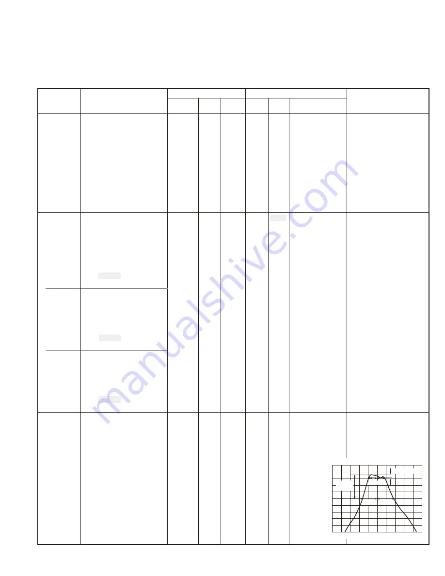
15dB or
more
−
8MHz +8MHz
−
20MHz
+20MHz
2.5dB MAX


