


KCH-16
15
1-3. Connecting the KCH-16 cable to the KRK-11
Interface box.
1. Connect the 8-pin connector of the KCH-16 cable to the
control connector (J2) of the KRK-11 Interface box.
■
Using the transceiver with two
KCH-16’s (For use with dual heads)
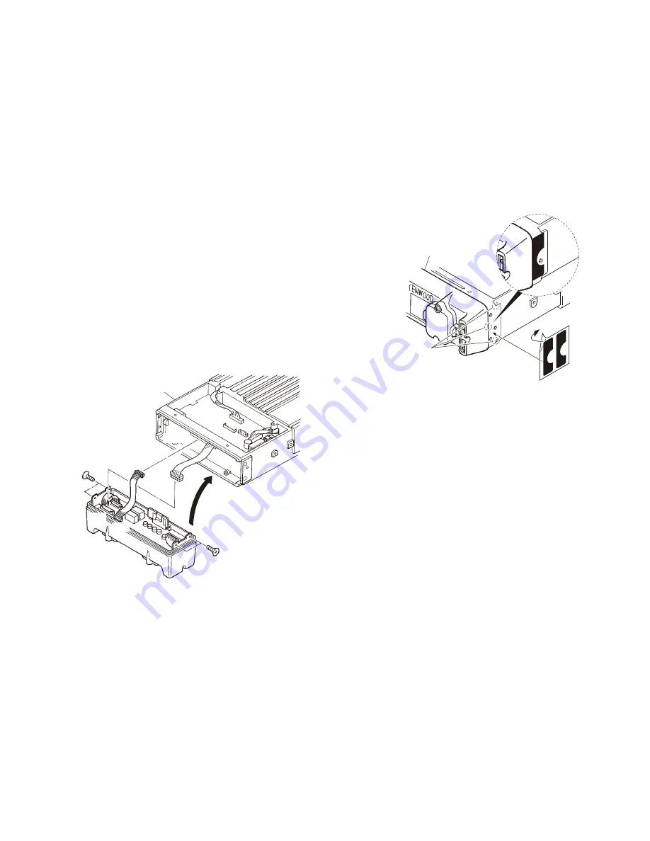
2-1. Installing the KRK-6DH main panel onto the
transceiver
1. Remove the upper and lower cases of the transceiver.
2. Insert the lead wire with connector (W700) from the
transceiver control unit (X53-412) to the connector (CN4)
of the KRK-6DH main panel.
Insert the lead wire with connector (W104) from the
KRK-6DH main panel to the connector (CN724) of the
transceiver.
3. Install the KRK-6DH main panel on the transceiver using
four screws (
q
).
Note:
Take care that the lead wire with connector (W700) is not
caught when fitting the KRK-6DH main panel onto the
transceiver.
KRK-6DH
main panel
W700
CN4
CN5
W104
CN724
Transceiver
:
:
Fig. 2-1-1
4. Affi xing the sheet (G11-4379-04) for waterproofi ng (Fig.
2-1-2).
(1) Remove the cover paper of the sheet (
w
).
(2)
Affi x the sheet while taking note of the position of the
three parts as shown in Fig.2-1-2 (
e
).
Firmly affi x the sheet to the chassis by pushing the
double-coated tape with your fi ngers.
(3)
Repeat step (2) to affi x the sheet to the other side of
chassis.
Note:
Take care that the sheet (G11-4379-04) does not peel off
when installing the upper/lower case.
5. Reassemble the upper case and lower case of the trans-
ceiver. (Refer to the TK-5710(B)/5710H(B) service manual
(B51-8727-10) (pages 25 and 26) or the TK-5810(B) ser-
vice manual (B51-8780-00) (page 23).)
Note:
Take care that the sheet (G11-4379-04) is not peeled off
when installing the upper/lower case.
Affix the sheet
while taking note of the
position of the three parts.
@
.
KRK-6DH main panel
Fig. 2-1-2
2-2. Connecting the KRK-6DH main panel and KRK-
11 Interface box using the KCT-22 control cable
1. Use two KCT-22 control cables. Insert one connector of
the fi rst control cable to the transceiver (with KRK-6DH
Head 1 side) and the other to the KRK-11 Interface box 1.
Insert one connector of the second control cable to the
transceiver (with KRK-6DH Head 2 side) and the other to
the KRK-11 Interface box 2.
Connect each GND cable to each GND terminal of the
KRK-6DH Head 1/Head 2 and KRK-11 Interface box 1/
Interface box 2 using the screw (
q
) supplied with each
control cable.
2. Secure the one connector of each control cable to the
KRK-6DH main panel Head 1/Head 2 using two screws
(
w
) according to the installation condition of the trans-
ceiver.
3. Pass the control cables through the grooves at both
ends of the KRK-6DH main panel and secure the control
cables to the KRK-6DH with the cable fi tting (J21-4354-04)
and the two screws (
e
) supplied with the KRK-6DH.
4. Secure the other connector of the control cable to the
KRK-11 Interface box 1/Interface box 2 with two screws
(
r
) in the same way.
INSTALLATION


