


KCH-16
16
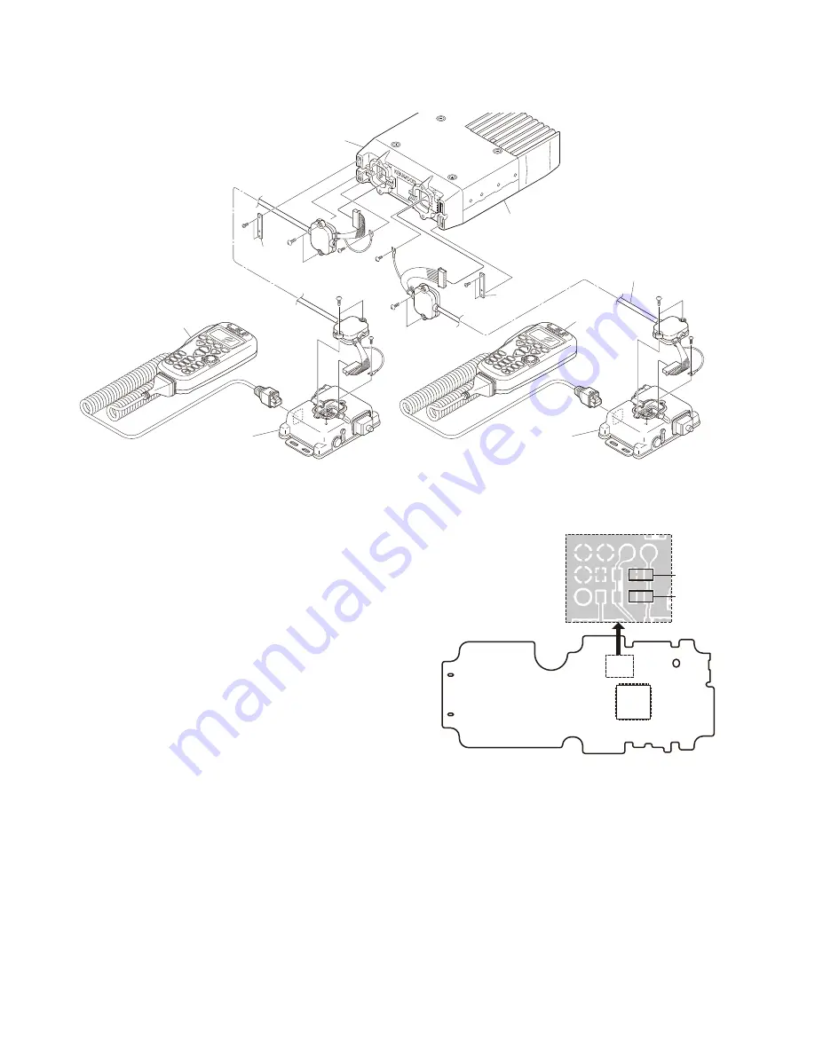
2-3. Connecting the KCH-16 (Head 1 side)/KCH-16
(Head 2 side) cable to the KRK-11 Interface
box 1/Interface box 2
1. Connect the 8-pin connectors of the KCH-16 (Head 1
side)/KCH-16 (Head 2 side) cable to the control connec-
tors (J2) of the the KRK-11 Interface box 1/Interface box 2.
Note:
When you use it as a dual head (combinations of KCH-16
and KCH-14/15 etc.), Generally connect the KCH-16 to
Head 1 side. The KCH-16 is set to the Head 1 side by
factory default.
It is necessary to perform modifi cation of “2-4. Modifi ca-
tion of the KCH-16 (Head 2 side)” if you use the KCH-16
on the Head 2 side.
2-4. Modifi cation of the KCH-16 (Head 2 side)
Perform the modifi cation of KCH-16 (Head 2 side) as fol-
lows.
1. Remove the chip resistor (R90).
2. Place the chip resistor (removed in step 1) on the R84
land pattern.
CONTROL UNIT
(X53-4360-20)
Foil side
R90
Head 1
Head 2
R84
Fig. 2-4
Note:
Connect the KCH-16 for Head 1 to the Head 1 side, and
the KCH-16 changed for Head 2 to the Head 2 side cor-
rectly, respectively.
When the KCH-16 for Head 1 is connected to the Head
2 side, or the KCH-16 changed for Head 2 is connected
with the Head 1 side, take care that voice is not be trans-
mitted even if the PTT switch is pressed and that the key
operations do not operate correctly.
Fig. 2-2
INSTALLATION
A
B
C
1
0
2
S
5
8
4
9
7
3
6
A
B
C
1
0
2
S
5
8
4
9
7
3
6
Transceiver
Cable
fitting
GND
Cable
fitting
GND
KRK-6DH
main panel
KCT-22
Control cable
KRK-11
Interface box 1
KCH-16
(Head 1 side)
KCH-16
(Head 2 side)
GND
J2
J2
KRK-11
Interface box 2
KCT-22
Control cable
GND
:
:
:
:
@
@
.
.
;
;


