


KCH-16
38
ADJUSTMENT
KCH-16
Item
Condition
Measurement
Adjustment
Specifi cations / Remarks
Test-
equipment
Unit
Terminal
Unit
Parts
Method
1. Setting
1) Connect the KCH-16 Hand-
held control head to the TK-
5710(B)/5710H(B)/5810(B)/
5810H(B) transceiver via the
KRK-11 Interface box and
KRK-11 Panel assembly.
2) Power supply voltage
•TK-5710(B)/5810(B)
Power input connector: 13.6V
•TK-5710H(B)/5810H(B)
Power input connector: 13.4V
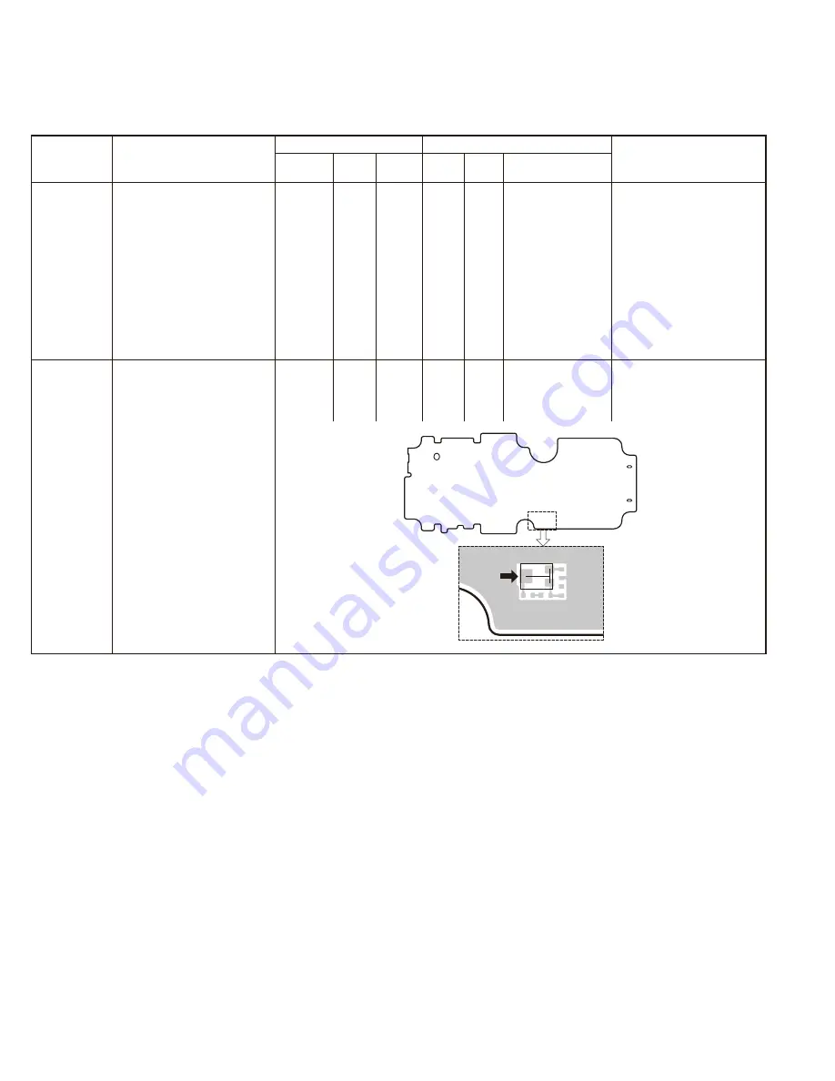
2. LCD
contrast
DVM
Control VR2
center
pin
Control VR2
Adjust the VR2 to
obtain the specifi ed
voltage.
0.87~0.91V
This item is needed when
the Control unit or LCD ASSY
(B38-0923-05) is replaced.
VR2
VR2
center
pin
CONTROL UNIT
(X53-4360-20)
Component side


