


Installation
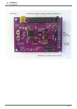
I/O Expansion
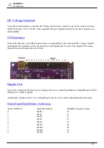
DC Voltage Selection
Using the provided jumper, select the DC Voltage which will be routed to each of the connector blocks.
Select from either 3.3V or 5V DC. This regulated voltage is supplied directly by the host computer (e.g.,
the RoboRIO).
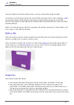
I/O Summary
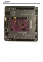
Each of the I/O pins on the MXP connector has a corresponding 3-pin connector (DC Voltage, Ground
and Signal). The orientation of the Ground, Power and Signal pins for each of the Digital I/O, Analog
Input and Analog Output pins is as follows:
Digital I/Os
Each of the 10 Digital I/O pins may be configured for use as either DigitalInputs or DigitalOutputs, PWM
(Outputs) or Counters (Inputs).
Additionally, multiple (either 2 or 3) DigitalInputs may be used to form an QuadratureEncoder input.
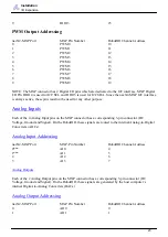
DigitalInput/DigitalOutput Addressing
navX2-MXP Port
MXP Pin Number
RoboRIO Channel Address
0
DIO0
10
1
DIO1
11
2
DIO2
12
3
DIO3
13
4
DIO8
18
5
DIO9
19
6
DIO10
20
7
DIO11
21
8
DIO12
22
22


