


Installation
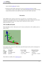
Orientation
Reference Frames
Note that the 3-axis coordinate system describes relative motion and orientation; it doesn’t specify the
orientation with respect to any other reference. For instance, what does “left” mean once a robot has
rotated 180 degrees?
To address this, the concept of a
was developed. There are three separate three-axis
“reference frames” that should be understood:
Coordinate
System
Technical Term
X Axis
Y Axis
Field
World Frame
Side of Field
Front (Head) of Field
Robot
Body Frame
Side of Robot
Front (Head) of Robot
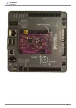
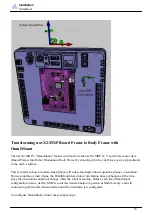
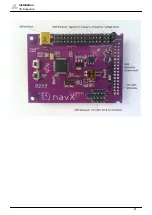
navX2 MXP Board Frame
See diagram Below
See diagram below
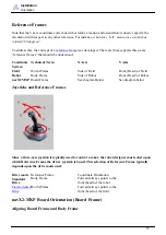
Joysticks and Reference Frames
Since a three-axis joystick is typically used to control a robot, the robot designer must select upon
which Reference Frame the driver joystick is based. This selection of Reference Frame typically
depends upon the drive mode used:
Drive mode Reference Frame
Coordinate Orientation
Standard
Drive
Body Frame
Forward always points to the
front (head) of the robot
Forward always points to the
front (head) of the field
navX2-MXP Board Orientation (Board Frame)
Aligning Board Frame and Body Frame
15


