Page 9
Copyright © 2012 Kato Engineering, Inc. All rights reserved
Assemble to prime mover, alignment
Follow either the two-bearing alignment (if your generator model has
two bearings but no adapter to bolt to an engine fl ywheel housing),
two-bearing close-coupled alignment (if your generator model has two
bearings and an adapter for bolting to a fl ywheel housing), or single-
bearing alignment (if your generator has one bearing and drive plates).
Consult the factory for belt or gear drive alignment).
Two-bearing close-coupled alignment
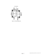
Check the engine fl ywheel housing pilot’s radial and face runout by
mounting a dial indicator and measuring the fl ywheel to the fl ywheel
housing as shown in Figure 2. See Table 1 for maximum allowable
runout.
NOTICES:
Mounting of the indicators must allow
complete rotation of the prime mover.
Use dial indicators that are rigid so indicator
sag won’t be a factor. Using the shortest
offset distance of the indicator bracket will
reduce the effects of indicator droop or sag.
During alignment, you may also need to
compensate for engine expansion due to
heating. Generator expansion is generally
not considered a factor.
If the genset is moved to a different
location, check alignment before startup.
WARNING: Do not pry on the
generator fan blades. The blades can
weaken, which could result in serious injury
or death from fl ying debris.
Figure 2: Flywheel housing check
Shaft
Flywheel
Flywheel housing
Dial indicator
pointer for radial
runout
Dial indicator pointer for
face runout


