background image

Page 43

Copyright © 2012 Kato Engineering, Inc. All rights reserved

NOTICE: Make sure all components are 
clean before assembly.

NOTICE: Torque fasteners to the values 
specifi ed in Table 3 unless otherwise speci-
fi ed.

NOTICE: Do not pound on the rectifi er or 
armature windings. Component damage 
may result.

Assembly

Bearing installation (done prior to installing the rotor)

1.   Heat the bearing to 220º F (104

C) - 250º F (121

o

 C) in a clean oven 

or with an induction heater. 

2.   Start the heated bearing on the shaft. Then use a fi ber or soft metal 

tube to tap the bearing into place. 

3.   Ensuring that pressure is applied only to the bearing inner ring, 

press the bearing onto the shaft until the inner ring seats against the 
bearing shoulder on the shaft. Assemble the rest of the generator after 
the bearing has cooled.

Overall assembly

1.  Float in the rotor until the rotor and stator laminations line up. 

Position the rotor such that a full pole face is at the bottom.

2.  Install the endbrackets. Support the rotor during installation. Put an 

corrosion inhibitor on the bare mating surfaces to prevent rust.

3.  Install the exciter armature and optional PMG as described below.

4.  Install the covers.

5.  Install the coupling or drive plates.

6.  Reconnect the load leads and exciter leads.

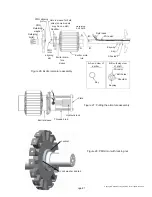
Exciter armature and PMG installation (see Figure 26)

1.   Clean the shaft and inside of the exciter sleeve.

2.   Place the key in the slot in the shaft.

3.   Lay the generator fi eld wires fl at in the wireway with the wire ends 

protruding past the end of the shaft.

4.   Position the exciter armature assembly in line with the shaft, and turn 

the assembly to the position where the keyway in the exciter sleeve is 
in line with the key in the generator shaft. 

5.   With hand force, push the exciter armature assembly over the shaft, 

so the end of the sleeve is against the shoulder on the shaft. When 
it is part of the way onto the shaft, start the fi eld lead wires through 
the wire hole or slot in the exciter sleeve. It may be necessary to tap 
lightly on the exciter sleeve in order to move the assembly over the 
key. Use a fi ber or rubber mallet. If installation is still a problem, use 
a heat gun to expand the exciter sleeve. 

Summary of Contents for Standard AC Generator

Page 1: ... 01001 00 01 19 2016 Please read this manual and all included manuals in its entirety before unpacking installing and operating your generator If your manual came on a CD read all the files included on the CD Kato Engineering P O Box 8447 Mankato MN USA 56002 8447 Tel 507 625 4011 Fax 507 345 2798 Email KatoEngineering emerson com www kato eng com Copyright 2015 Kato Engineering Inc All rights res...

Page 2: ...earing alignment 18 Foot deflection 23 Doweling 23 Electrical connections 23 Space heaters 23 Inspection before startup 23 Operation 25 Initial startup generators w auto manual control 25 Initial startup generators w auto control only 25 Restoring residual magnetism field flashing 26 Continuous operation 27 Idling 27 Parallel operation 27 Notice Because of rapid changes in designs and processes an...

Page 3: ... voltage 35 Dry out procedures 36 Bearing lubrication 36 Rectifier tests 37 Disassembly 39 Overall disassembly 39 Exciter armature and PMG removal 40 Bearing removal 42 Assembly 43 Bearing installation 43 Overall assembly 43 Exciter armature and PMG installation 43 Storage 45 Torque chart 46 47 Troubleshooting Guide 48 Main part location 51 List of equipment required for installation and maintenan...

Page 4: ...cannot be completely defined by any manual nor built into any piece of equipment the following paragraphs define warnings cautions Notices and Important as they are used in this manual WARNING Warnings identify an installation operating or maintenance procedure practice condition or statement that if not strictly followed could result in death or serious injury to personnel CAUTION Cautions identi...

Page 5: ... wire wound around each pole V blocks between each pole keep the rotor windings in place Damper windings consist of copper or aluminum rods that are inserted through each pole surface and are brazed to copper or aluminum damper end plates at each end of the lamination stack The end plates are brazed to adjacent poles to form a continuous damper winding The ends of the windings are supported with b...

Page 6: ...the voltage regulator The assembly consists of two subassemblies the exciter armature and the rotating rectifier The exciter armature assembly contains steel laminations that are stacked and keyed on the shaft or on to a sleeve which is keyed to the generator shaft A three phase winding is inserted into slots in the laminations The coils are held in place by insulating wedges The coil extensions a...

Page 7: ... position The PMG rotor consists of rectangular permanent magnets and cast pole tips secured to a steel hub with nonmagnetic stainless steel bolts The PMG rotor is keyed to the shaft and secured with a nut and lock washer PMG system overview The PMG system functions as a pilot exciter providing power to the automatic voltage regulator power supply The PMG is an AC generator that uses permanent mag...

Page 8: ...sulation resistance before placing the generator in operation see the maintenance section Protect generators operating intermittently in very damp locations with space heaters Slowly warm generators placed in operation after being subjected to very low temperatures to prevent excessive condensation Base design The type of base to be used will depend upon the nature of the installation site However...

Page 9: ... to the flywheel housing as shown in Figure 2 See Table 1 for maximum allowable runout NOTICES Mounting of the indicators must allow complete rotation of the prime mover Use dial indicators that are rigid so indicator sag won t be a factor Using the shortest offset distance of the indicator bracket will reduce the effects of indicator droop or sag During alignment you may also need to compensate f...

Page 10: ... TIR Total indicated runout NOTICE Compensation for engine thermal growth must be taken into account on this measurement SAE housing number 6 5 4 3 2 1 0 5 0 00 10 500 12 375 14 250 16 125 17 625 20 125 23 000 25 500 31 000 Housing inside dia Table 1 Maximum allowable flywheel housing runout inches Figure 3 Flywheel check Shaft Flywheel Flywheel housing Dial indicator pointer for radial runout Dia...

Page 11: ... not considered a factor If the genset is moved to a different location check alignment before startup WARNING Do not pry on the generator fan blades Blades can weaken which could result in serious injury or death from flying debris NOTICE Generators equipped with sleeve oil bearings must have oil added to the bearing prior to rotation Failure to comply will result in bearing damage See the bearin...

Page 12: ...will allow for the thermal growth of the shaft Mount the generator on the skid and move the generator to within 0 010 inch of the engine Place two 0 010 inch shims in the horizontal 9 o clock and 3 o clock positions between the generator adapter and the engine flywheel housing Raising the rear exciter end of the generator as necessary place two 0 010 inch shims in the vertical 6 o clock and 12 o c...

Page 13: ...and runout check remove the horizontal shims from the adaptor flywheel housing and move the generator all the way to the adaptor Then tighten the fasteners Recheck alignment Make sure angularity face total indicated runout does not exceed 0 005 inch per inch of generator coupling diameter and parallel radial total indicated runout does not exceed 0 005 TIR Torque the fasteners to the value shown i...

Page 14: ...t all the way to the engine then back off that location 020 or 508mm This will allow for the thermal growth of the shaft If the generator has floating bearings align the face of the outer seat with the groove in the shaft electrical center Two bearing alignment Follow the tolerances specified by the coupling manufacturer when they are less than described in this manual Use shims if necessary betwe...

Page 15: ...s gauge for rough alignment as shown in Figure 10 Check for angular and parallel alignment as follows Figure 10 Rough alignment Straight edge Thickness gauge Shaft Flywheel Flywheel housing Dial indicator pointer for radial runout Dial indicator pointer for face runout Figure 9 Engine coupling check ...

Page 16: ...component from side to side until the components are properly aligned Tighten the mounting bolts and recheck alignment Parallel alignment Fasten a dial indicator to one of the coupling halves and scribe the position of the dial button on the top of the opposite coupling half as shown in Figure 12 Rotate both shafts simultaneously keeping the finger or button on the indicator at the reference mark ...

Page 17: ...Page 17 Copyright 2012 Kato Engineering Inc All rights reserved Dial indicator Figure 12 Parallel alignment ...

Page 18: ...the flywheel housing as shown in Figure 5 See Table 1 for maximum allowable runout Check the engine flywheel s radial and face runout by mounting a dial indicator and measuring the flywheel housing to the flywheel as shown in Figure 3 See Table 2 for maximum allowable runout Measure the generator drive plate diameter dimension S of Figure 14 and flywheel bore diameter dimension B of Figure 15 Driv...

Page 19: ...n G in Figure 15 Make sure the difference between dimensions Y of Figure 14 and G are less than 1 32 inch If G is more than Y install additional spacers between the drive discs and the generator hub If Y is more than G remove spacers between the drive discs and generator hub Figure 14 Single bearing generator drive plate and adaptor S Y W A Adaptor Bolt holes Drive plates Fan Shaft WARNING Never g...

Page 20: ...n will typically occur with several types of generators With the three frame units that have an aluminum fan loosen the fan hub bolts to move the fan After installing the drive disc to flywheel bolts move the fan back so the rotor side edge is flush with the air opening and the minimum distance between the windings and the fan is 3 8 inch Torque the fan hub bolts to 75 ft lbs With sheet metal fans...

Page 21: ...Set screw Key Bolt holes Alignment mark on drive hub Fan hub bolt Fan hub Keyway Drive discs Fan Fan bolts Figure 17 Moving sheet metal fans IMPORTANT The generator with sheet metal fans and cast fan hubs is shipped from the factory with the fan 1 2 to 3 4 inch from the fan baffle and clear of the inside adaptor for optimum air flow through the exhaust screen ...

Page 22: ...n Figure 18 If the total indicated runout exceeds 0 003 inch remove the drive discs bolts and rotate the generator relative to the engine flywheel Reinstall the bolts and check the runout again Recheck the shaft end to bearing housing distance dimension A in Figure 13 Mount the brushless exciter armature assembly to the generator shaft as described in the assembly procedures below Figure 18 Runout...

Page 23: ...e heater AVR in accordance with local regulations and national international electrical code requirements Check the electrical diagrams provided with the generator or manual The main terminals need to be properly spaced for the load connections Refer to Table 3 for the proper torque values for the connections On larger generators grounding points are provided for properly grounding the system to t...

Page 24: ...ngine generator set is protected with an adequate engine governor and against excessive overspeed Make sure the output of the generator is protected with an overload protection device such as circuit breakers or fuses sized in accordance with national international electrical code and local electrical code standards Fuses need to be sized using the lowest possible current rating above the full loa...

Page 25: ...er and stop the prime mover 6 Actuate the auto voltage rheostat Then start the genset and bring it to rated speed Adjust the voltage to the desired value 7 Close the output circuit breaker Then check the generator voltage and voltage regulation Apply load in steps until the rated load is reached 8 Check for vibration levels at no load and rated load A slight increase is normal As the load is maint...

Page 26: ... voltage build up connect a 12 or 24 volt battery to the exciter field coil circuit and flash as follows 1 Open the output circuit breaker and stop the engine 2 Disconnect the exciter field coil wires EF1 at the terminal EF1 and EF2 at the terminal EF2 and connect the battery positive lead to the field coil lead EF1 3 Flash the field by touching the battery lead to the field coil circuit terminal ...

Page 27: ...rmissible allowable unbalance region for safe operation of the generator Loss of field excitation can result in the unit operating out of synchronization with the system when operating is parallel This has the effect of producing high currents in the rotor which will cause damage very quickly Protective relays should be considered to open the circuit breaker Idling Unless the voltage regulator has...

Page 28: ...nd the V Hz regulation characteristics must be the same for all the voltage regulators This will allow the generators to properly share reactive loads If cross current compensation is used paralleling current transformers must give the same secondary current Current transformer secondary windings provide reactive kVA droop signal to the voltage regulator Accidental reversal of this electrical wiri...

Page 29: ...nerator operating in parallel gradually reduce the kW load by using the governor to reduce speed When kW load and line current approach 0 open the generator circuit breaker Operate the generator unloaded for several minutes to dissipate the heat in the windings Refer to the prime mover manual for shutdown and cool down procedures Figure 20 Guide to allowable phase unbalance 0 20 40 60 80 100 20 40...

Page 30: ...r proper stability and voltage output Monitor the power factor and generator loading during operation With generators that have sleeve oil bearings check the operating temperatures and sight glass levels if applicable Every week Visually inspect the bearing exterior for dirt and clean if necessary Inspect any generator air filters for build up of contaminants and clean or replace as required Every...

Page 31: ...l Every 20 000 hours or 3 years of operation With generators that have sleeve oil bearings perform a sleeve bearing inspection to include the removal of the upper bearing housing and bearing liner to inspect the liner shaft journal and seal surfaces for wear or scoring Remove the endbrackets and visually inspect the generator end windings for oil or dirt contamination Excessive contamination may n...

Page 32: ...ticles industrial chemicals such as acids solvents and cleaning solutions Physical damage This contributes to electrical insulation failure by opening leakage paths through the insulation Physical damages can be caused by physical shock vibration over speed short circuit forces or line starting out of phase paralleling erosion by foreign matter damage by foreign objects and thermal cycling Ionizat...

Page 33: ...al surfaces Use a vacuum to clean ventilating ports Windings assembled machines Where cleaning is required at the installation site and complete disassembly of the machine is unnecessary or not feasible pick up dry dirt dust or carbon with a vacuum cleaner to prevent the redistribution of the contaminant A small non conducting nozzle or tube connected to the vacuum cleaner may be required to reach...

Page 34: ...e voltage regulator 2 Connect exciter leads to one clamp of 500 volt megger and connect the other clamp to the exciter field frame 3 Apply 500 V from the megger and measure the resistance reading after 1 minute The reading must be a minimum of 50 megohm If it is not refer to the cleaning or dry out procedures 4 Ground the exciter field leads to the exciter field frame for several minutes after the...

Page 35: ...the megger This will allow the voltage build up to be properly discharged Main rotor 1 Disconnect the generator field leads from the positive and negative terminals of the rotating rectifier assembly 2 Connect the positive and negative leads to one clamp of the megger and connect the other clamp to the shaft 3 Apply voltage from the megger and measure the resistance reading after 1 minute The read...

Page 36: ...lation resistance values level off Monitor winding temperatures Raise winding temperature gradually at a rate of 10 20 F 12 to 6 C per hour up to 200 F 93 C Measure insulation resistance at 1 hour intervals Typically the insulation resistance will slowly drop while the temperature is coming up and then gradually increase and level out Bearing lubrication Shielded or sealed ball bearings Shielded o...

Page 37: ...Lift the rectifier from the heat sink see figure 22 for an overview Test the entire rectifier with an ohmmeter or test lamp as follows Ohmmeter Connect the ohmmeter leads across the rectifier in one direction see Figure 23 Notice the meter reading Reverse the leads and Notice the meter reading The meter should indicate a low resistance when the leads are across the rectifier in one direction and a...

Page 38: ...n the generator at the factory Order rectifiers by part number including the model and type of exciter as well as the generator serial number Surge protectors may be included on the rotating rectifier assembly Disconnect one lead of the surge protector and connect the leads of an ohmeter or makeshift test lamp consisting of standard flashlight batteries and a flashlight and built as shown in Figur...

Page 39: ...stages of movement Make sure the rotor does not hit the stator Disassembly Overall disassembly 1 Remove the terminal box cover and disconnect the load leads and all other leads Tag the leads to ensure they are correctly connected when the generator is reassembled 2 Remove the bolts securing the generator to the base and prime mover and move the generator to an area that allows sufficient room for ...

Page 40: ...Pull the PMG rotor straight back Take care not to cock the PMA when pulling it off c Wrap the PMG rotor in plastic to avoid contamination with metal filings 5 Slowly pull the armature assembly off of the generator shaft If the exciter can not be pulled off by hand use a hydraulic jack as shown in Figure 27 6 Remove the key from the keyway in the generator shaft NOTICE Ensure the generator field wi...

Page 41: ...ning slot Exciter arma ture sleeve Exciter arma ture A A B B Retaining bolt hole Field leads Wire slot Keyway Key Shoulder A A end view of exciter Key Keyway Shoulder Bolt holes Wire slot B B cutaway view of shaft Figure 26 Exciter armature assembly Figure 27 Pulling the armature assembly Plate Hydraulic jack Threaded rod Exciter sleeve Figure 28 PMG rotor with locking nut Lock washer and tab Lock...

Page 42: ...xpose the bearing s 2 Use a puller to remove the bearing from the shaft end with a cap If the bearing is going to be used again make sure the puller supplies pressure only against the bearing inner ring see Figure 29 Puller against bearing Cap to protect shaft end Outer ring Inner ring Figure 29 Bearing removal ...

Page 43: ...rt the rotor during installation Put an corrosion inhibitor on the bare mating surfaces to prevent rust 3 Install the exciter armature and optional PMG as described below 4 Install the covers 5 Install the coupling or drive plates 6 Reconnect the load leads and exciter leads Exciter armature and PMG installation see Figure 26 1 Clean the shaft and inside of the exciter sleeve 2 Place the key in th...

Page 44: ...mature and exciter field and between the PMG rotor and PMG stator If the air gap of the armature is less than specified in Table 5 or if the air gap of the PMG is less than 0 020 inch check 1 generator engine alignment 2 check for bearing wear 3 check for misalignment of the armature PMG or stator 11 Install the exciter cover Exciter armature diameter in 0 014 0 014 0 018 0 035 Minimum air gap in ...

Page 45: ...ld be in an ambient temperature of approximately normal room temperature Protect the shaft from corrosion by applying an anti corrosion agent Cover the unit with a durable cover Prepare units that cannot be stored in a temperature and humidity controlled area as follows Install desiccant bags in the exciter cover and inside the end bells Vacuum seal the unit in a covering of plastic or other mater...

Page 46: ...00 400 Inch pounds ASTM and SAE Torque Values Grade 5 Grade 8 Foot Pound Foot Pound Newton Meter Newton Meter Grade 5 GASKETED COVERS SCREW SIZE Grade 2 Foot Pounds Newton Meter Newton Meter Foot Pound Inch pounds Ft Lbs Tol N M Tol Ft Lbs Tol N M Tol Ft Lbs Tol N M Tol Ft Lbs Tol N M Tol 4 40 4 0 4 5 0 6 6 32 8 0 9 10 1 1 8 32 20 2 3 16 1 8 21 2 4 10 24 18 2 24 2 7 10 32 34 3 8 33 2 9 33 3 7 1 4 ...

Page 47: ...15 95 20 M12 x 1 75 34 7 45 9 58 7 77 15 19 4 26 5 83 20 135 27 M14 x 2 00 54 10 72 13 94 10 125 23 132 30 200 40 M16 x 2 00 80 13 108 18 144 13 192 32 196 40 275 55 M18 x 2 50 114 22 152 29 190 22 253 50 269 50 500 70 M20 x 2 50 162 23 216 30 260 23 347 50 366 60 800 80 M22 x 2 50 202 23 269 31 368 23 491 55 520 90 1200 120 M24 x 3 00 245 25 327 33 470 25 627 65 664 120 1650 160 M27 x 3 00 360 40...

Page 48: ... the windings Return the generator to the factory for repair if open Malfunction of automatic voltage regulator See troubleshooting of voltage regulator Correct deficiencies Short circuited generator output leads Clear lead to restore voltage buildup Open in rotating rectifiers Check rotating rectifiers and replace if open Open in generator field Check for continuity and return rotor to factory fo...

Page 49: ...providing the generator temperature rating stamped on the nameplate is not exceeded Defective rectifiers in rectifier assembly stationary Check rectifier assembly Replace defective fuses or rectifiers Excessive load Reduce load to rated value Defective bearing Replace the bearing Improper speed of engine driven generator set due to defective governor ignition system or carburetor Check and correct...

Page 50: ...eld coils for shorts Replace shorted rotor or return it to the factory for repair Unbalanced load or overload low PF Adjust load to nameplate rating Vibrations Defective or dry bearings Replace defective bearings Misalignment of generator and prime mover Align the generator set Generator not properly mounted Check mounting Correct defective mounting Transfer of vibration from another source Isolat...

Page 51: ... light Screwdrivers Standard sized as required Screwdrivers Phillips sized as required Wrench Adjustable 12 inch Wrench Torque 0 to 100 ft lb Wrench set Allen 1 8 to 1 2 inch Wrench set Socket 1 4 to 1 Inch with 3 8 and 1 2 inch drive Wrench set Standard open end box end combination sized 1 4 to 1 inch Vacuum Electric with nonmetallic nozzle Materials Air Compressed dry Corrosion inhibitor Nox Rus...

Page 52: ...Page 52 Copyright 2012 Kato Engineering Inc All rights reserved Main part location Rotor Stator windings Feet Bearing Coupling hub Adapter Fan Drip proof cover Lead connection box ...

Reviews: