Page 20
Copyright © 2012 Kato Engineering, Inc. All rights reserved
Install the generator to the engine. Make sure the drive discs seat in
the recess of the fl ywheel housing. Secure the generator to the engine
(drive discs to fl ywheel, adapter to fl ywheel housing), and the base. Use
lock washers on all bolts. Torque the adapter and drive discs in a criss-
cross pattern to the values in Table 3.
Ensure that the bolts in the fl ywheel do not bottom out. If they are too
long or cannot be tightened with a socket or box wrench, use 1/4 to 3/8-
inch long spacers inserted in the bolts as shown in Figure 16 to increase
the clearance between the bolt head and the fl ywheel.
Occasionally, there is insuffi cient clearance to install the bolts that
fasten the drive discs to the engine fl ywheel, and the fan will have to be
temporarily moved to accommodate this. This situation will typically
occur with several types of generators:
• With the three-frame units that have an aluminum fan, loosen the fan
hub bolts to move the fan. After installing the drive disc-to-fl ywheel
bolts, move the fan back so the rotor-side edge is fl ush with the air
opening and the minimum distance between the windings and the
fan is 3/8 inch. Torque the fan hub bolts to 75 ft-lbs.
• With sheet metal fans with cast hubs that are in turn mounted on the
drive hub, mark the drive hub as closes as possible to the fan hub.
Loosen the two set screws, the fan clamping bolt, and the fan bolts.
Wedge the fan open, and move it out of the way (See Figure 17).
After attaching the drive discs-to-fl y wheel bolts, align the fan hub
to the mark to move the fan back to its original position. Ensure
the key is fully in place under the fan hub and positioned so the set
screw will press on the key. Tighten the fan hub clamping bolt and
the set screws. Install the fan bolts and torque them according to
Table 3.
B
C
G
Tapped
bolt holes
Flywheel
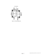
Figure 15: SAE fl ywheel and adapter


