Page 41
Copyright © 2012 Kato Engineering, Inc. All rights reserved
Hole in sleeve for fi eld
wires (some models
may have a slot)
PMG aligning
pin
PMG
Retaining
washer
Retaining
bolts
Rectifi er
PMG
rotor
aligning
slot
Exciter arma-
ture
sleeve
Exciter arma-
ture
A
A
B
B
Retaining
bolt hole
Field leads
Wire slot
Keyway
Key
Shoulder
A-A end view of
exciter
Key
Keyway
Shoulder
Bolt holes
Wire slot
B-B cutaway view
of shaft
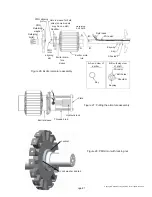
Figure 26: Exciter armature assembly
Figure 27: Pulling the armature assembly
Plate
Hydraulic jack
Threaded rod
Exciter sleeve
Figure 28: PMG rotor with locking nut
Lock washer and tab
Locknut


