background image

 33


8.


Your computer should now show the same image as shown on your local Spectra Connect


7.


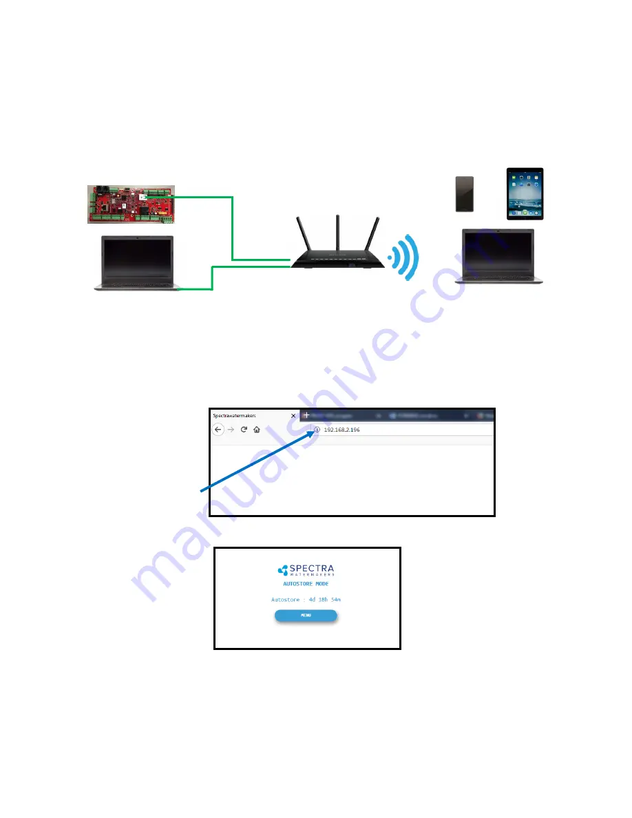
On the computer, tablet or smartphone, open a web browser such as Firefox, Chrome, or 
Safari.  In the web address bar at the top, type the 

Device IP

’ 

address previously recorded.  

Press 

Enter

’.


Note: 

Internet Explorer may not be compatible with your Spectra Connect web app.  If 

formatting issues occur, use another browser such as Firefox, Safari, or Chrome.


Ex: Address Bar—Firefox


9.


Your web browser is now synced with your Spectra Connect.  Any buttons you press on 
your web browser will be controlling your watermaker.


Caution! 

If operating your watermaker from a computer, phone, or tablet, you must keep 

the tab open while the system is in operation and the volume turned up on your device in 
order to hear any audible alarm faults.


Connecting to the existing Network—Cont

d


Ship

s Router or Switch


6.


Connect your computer, tablet or smart phone to the local network your Spectra Connect 
is plugged into.  


Wired Connection:

 simply plug your computer

s ethernet port directly into the router 


or switch where you connected the watermaker.


Wireless Connection:

 make sure your device is connected to the same local wireless 


network as the Spectra Connect


Wired Connection


Wireless Connections


Summary of Contents for Spectra Catalina 340C

Page 1: ...on and Operating Manual Spectra Watermakers info spectrawatermakers com Katadyn Desalination LLC www spectrawatermakers com 2220 S McDowell Blvd Ext Petaluma CA 94954 Phone 415 526 2780 Fax 415 526 27...

Page 2: ...2...

Page 3: ...reen Spectra Connect Quick Start Guide Run Mode Select your desired Run Mode to start making water and filling your tanks See details on Run Mode options on p 37 Spectra Connect Modes and Definitions...

Page 4: ...ty will be void if the installation does not meet this requirement 3 Follow the wire gauge charts in the instructions Using larger wire than specified is acceptable 4 If you are separating the Clark P...

Page 5: ...oduct Flow Calibration 31 Networking 32 Normal Operation 34 Maintenance Storage and Troubleshooting Maintenance 39 Introduction to Spectra Chemicals 42 Storage Procedures 44 Winterizing with Propylene...

Page 6: ...CITING EXTENDED WARRANTY OFFER Upgrade the standard 1 YEAR manufacturer warranty to 2 YEARS and LIFETIME on Clark Pump Follow the below steps to submit for approval 1 Have system installed commissione...

Page 7: ...lation Lay out the system Before starting the installation identify where each module and component will be placed Ensure that there is enough clearance around the components for removal of filters an...

Page 8: ...ittent flow restrictions air bubbles contaminants and will void the warranty For racing boats and high speed boats traveling above 15 knots a retractable snorkel type thru hull fitting is preferred be...

Page 9: ...48 C Sea Strainer and Boost Pump Module Mount close to the intake through hull below the waterline in a location that can handle water spillage during service The boost pump power cable will connect t...

Page 10: ...occurs Allow for easy access to the pressure relief valve The Clark pump and membrane module comes complete with a mounting system Be sure to use the supplied washers on the rubber feet Pressure Reli...

Page 11: ...verboard fitting Plumbing Schematic Flush water from ship s pressure water system 25 psi 2bar minimum and 50 psi 3 5bar maximum Use part of the 25 feet 8 meters of 1 2 inch vinyl hose pre fitted with...

Page 12: ...at is unattended for the fresh water flush system to function properly The domestic fresh water pump must be able to deliver 1 5 gallons per minute 6 LPM at 25 PSI 1 7 bar Attaching 1 2 inch vinyl hos...

Page 13: ...itting from the installation kit From the feed pump to the Clark Pump feed water inlet use the remaining 1 2 inch vinyl hose with the 1 2 inch John Guest stem fitting pre fitted with a ferrule Insert...

Page 14: ...m until the Connect controller determines the product water is below 750 PPM salinity Once below 750 PPM the Connect controller opens the diversion valve and product water is diverted into the fresh w...

Page 15: ...15 John Guest Super Speedfit Fittings...

Page 16: ...w access to the motor speed control Power inlet harness with terminal block Boost pump cable Yellow Motor speed controller Spectra Connect controller Inside control box Run Auto Manual Service toggle...

Page 17: ...t 15M cable for the Connect display Diversion Valve and Rotoflow Cable 5 conductor Red Z Ion power and signal cable 3 conductor Green Cables are shown coming out of the bottom of the Feed Pump Module...

Page 18: ...bles accordingly Mount the main power terminal block in a junction box or on a bulkhead adjacent to the feed pump module Make sure that this is a dry location well above bilge level and not subject to...

Page 19: ...g the wire or sharp corners where the wire can chafe through while the vessel is under way Turn power OFF to the system Connect the ethernet cable to back of the display in the open jack Connect the o...

Page 20: ...or Instructions on Auto Fill mode and installing a Tank Low switch see Auto Fill mode instructions later in this manual Watermakers should never be run unattended Your watermaker comes with the top mo...

Page 21: ...user commands Drill 5 8 hole into the side of the fresh water tank that is being filled by the watermaker This can be installed wherever there in convenient access to the tank approximately 2 3rds of...

Page 22: ...sh Water Tank Domestic Water Pump Connect Red to Red White to White Black to Black If a 2nd Tank Level Sensor is going to be installed it should be installed at the base of the second tank If monitori...

Page 23: ...he section Dry Testing with an Artificial Ocean 1 First Check That Seacock is open Toggle switch on the Feed Pump Module is in the Run Auto position Domestic fresh water pressure system is on 2 Open p...

Page 24: ...stem Shut down the system and repair any leaks you find Check the strainer and the brine discharge for water flow The system should fully prime within 60 90 seconds and all air should be out of the fe...

Page 25: ...water from the brine discharge service hose hose attached to Clark Pump Press Stop when the bucket is full 6 Mix the salt to the proper proportion or use an aquarium hydrometer to adjust the salinity...

Page 26: ...an and all thru hulls are open before proceeding 2 Follow the steps in Figures 1 4 below to initiate the Calibration Sequence Sensor Calibration Many of the settings on your system have been pre calib...

Page 27: ...pump needs to be slowed down Slowing down the pump during a Fresh Water Flush Inside the feed pump module under the Conn box is the pump speed controller On the speed controller board are two magneti...

Page 28: ...ge in a clean cup Measure the salinity of the brine discharge and confirm that it is below 1000ppm using a calibrated hand held TDS meter If the flush duration needs to be increased seek the Spectra C...

Page 29: ...eet Meter field to enter the tank height in feet meters Press the Inch cm field to enter the height in inches Ex If the Tank height is 150cm Enter 1 in the field labeled Meter Enter 50 in the field la...

Page 30: ...ampling valve was installed 7 Touch the PPM field and enter the reading taken above 8 Press Proceed to store the new calibration value You must save all changes when prompted after exiting the setting...

Page 31: ...3 7 Touch the seconds field to enter the seconds it took to fill the container Only enter the seconds ex 3 min 15 sec should be entered as 15 8 Press Proceed You must save all changes when prompted af...

Page 32: ...system back on 4 Follow the screen prompts below 5 Note the line Device IP shown in Fig 3 and record the 10 digit numerical address on the front of this manual Fig 1 Fig 2 Fig 3 Note Your Spectra Con...

Page 33: ...you press on your web browser will be controlling your watermaker Caution If operating your watermaker from a computer phone or tablet you must keep the tab open while the system is in operation and t...

Page 34: ...ic pressurized water system is turned on 2 Press the Start button then select the desired operating mode Runs your watermaker until the Tank Full switch closes fresh water flushes the system then goes...

Page 35: ...Valve Status CLOSED Diversion Valve Status OPEN 6 When the Product Water Quality is below the programmed threshold the Diversion Valve opens allowing water to enter the tanks and the screen image cha...

Page 36: ...0 100psi 110 psi 7 6 Bar Boost Pressure 15 psi 1 1 Bar or Greater Filter Condition 100 Amp Draw 19A 12 5vdc 9 5A 25vdc 8 When the Run Cycle completes or by pressing Stop the system will start to Fresh...

Page 37: ...enu will allow the system to be operated in Auto Fill mode WARNING NEVER RUN YOUR WATERMAKER UNATTENDED EQUIMENT CAN BE SERIOUSLY DAMAGED AND IT IS POSSIBLE TO SINK THE VESSEL Use extreme caution when...

Page 38: ...the expected time of operation in the Auto Store mode If there isn t enough fresh water in your tank seawater will be drawn in and the system will not be flushed with fresh water The Catalina 340c re...

Page 39: ...mble dry to impede corrosion Check frequently during operation The Pre filters Service the pre filters as soon as possible after the pre filter condition graph begins to rise If the filter condition g...

Page 40: ...n the back of the Clark Pump have captive nuts and washers which compress the O rings without turning the entire fitting If a tube fitting leaks it can sometimes be resealed by just tightening You mus...

Page 41: ...r a higher salinity seawater source can cause high pressure Low product flow is usually due to low voltage a worn feed pump or worn Clark Pump Due to the unique design of your Spectra system low produ...

Page 42: ...tructions for Storage Procedure Spectra systems should be stored with propylene glycol if freezing is likely to occur Propylene glycol can be used instead of Spectra SC 1 storage chemical for storage...

Page 43: ...perience low product water quality cleaning with SC 2 usually removes all traces of propylene glycol and returns the salinity to the level it was before storage with propylene glycol See the Membrane...

Page 44: ...rclockwise 8 Turn on the feed pump by moving the manual control switch on the control box to SERVICE The solution will be drawn from the bucket with the service hose and returned to the bucket from th...

Page 45: ...water Stop the pump by moving the switch back to RUN AUTO Add more propylene glycol to the intake bucket if necessary 7 Lead the brine discharge service hose into the intake bucket of propylene glycol...

Page 46: ...5 Make sure that the pressure relief valve on the Clark Pump is open un pressurized 6 Mix the cleaning chemical in the bucket If possible heat the solution to 120 F 49 C 7 Move manual switch on the Fe...

Page 47: ...g chemicals One replacement strainer screen replacement O ring for strainer screen and replacement O rings for the filter housings Common Parts Item Part Number SC 1 STORAGE CHEMICAL KIT CHEM SC1 SC 2...

Page 48: ...ontact factory Close pressure relief valve No lights or display system does not operate Remote display not connected No power to control box Check display cable connections at back of display and at c...

Page 49: ...Too Low Battery voltage too high or low Loose wires or poor connections Charge batteries Check charging voltage Check power connections Check Fuse followed by fuse number Blown fuse at circuit board...

Page 50: ...50 This page intentionally left blank...

Page 51: ...k pump does not cycle if air is continuously present in the intake line or if the feed pump is excessively noisy Always discard the product water for the first few minutes of operation as the initial...

Page 52: ...noted continue with this test You will need a graduated bucket either a graduated pitcher or large measuring cup and a stopwatch Log the voltage at the feed pump at the same time Confirm at least 12 5...

Page 53: ...le It took 53 seconds to collect 12 liters of total flow 60 53 x 12 13 58 LPM 3 Recovery Rate Product Flow Total Flow Recovery Rate Example 6 5 GPH product flow 063 or 6 3 1 7 GPM total flow x 60 you...

Page 54: ...flush water They must be of proper specification to be suitable See page 64 There is no test for chlorine damage except the process of elimination of other causes DIRTY OR SCALED membranes A dirty for...

Page 55: ...and the Clark Pump The purpose of the feed line accumulator is to reduce the spikes in the feed pressure caused by the cycling of the Clark Pump If the accumulator is not properly charged it can lead...

Page 56: ...filter will plug up water production and quality will drop and the system pressure will change dramatically In blue water conditions the pre filter may only need to be changed every week or two When...

Page 57: ...there are aftermarket filters which are very close to but not exactly the right dimensions and they will not seal in the housing If you skimp on the charcoal filter you risk damaging a 600 00 membrane...

Page 58: ...easier than ever The onboard time clock feature allows for temporary power interruptions without detrimental effects on the system In some cases your watermaker will continue to function in its last...

Page 59: ...sensor System stalled alarms occur when the control board does not sense any product water being produced and shuts down to protect the pump from running dry Poor Quality Fault Disables the High Salin...

Page 60: ...lear Statistics Resets all of the Estimated Maintenance Intervals back to 100 This feature should only be used on a brand new system Change Username password Changes the default username and password...

Page 61: ...sors which read the remaining in the tank and the tank switches which allow the system to turn on off automatically Boost Pressure Setup Enable alternate Boost Pressure sensors change the Low Vacuum L...

Page 62: ...les or disables an optional power sensor after it is installed PH ORP Enables an optional pH or ORP meter after it is installed Z Ion Enables or Disables the optional Z Ion system after it is installe...

Page 63: ...intake line for restrictions blockages or air leaks Close Pressure Relief Valve on Pump Confirm controller settings correct SERVICE PREFILTER FAULT The Service Prefilter fault is triggered if Inlet Pr...

Page 64: ...64 Wiring Schematic...

Page 65: ...voltage limits 10 32vdc Outputs 5VDC 2000mA Total for all outputs VLV 1 2 1 Amp DC priming valve solenoid AUX 1 3 1 Amp DC auxiliary output Never connected anything to the Spectra Connect without fac...

Page 66: ...g SUB CT Z HPILHA CT 340c Quick Disconnect PL TEE 1 2TJG John Guest 1 2 inch swivel tee PL STA 12Tx38NJ 1 2 Tube Stem x 3 8 NPT adapter John Guest Accumulator Hose 20 inches 1 2 inch vinyl hose PL HS...

Page 67: ...upler Panel FT FTC 5 5 MICRON FILTER ELEMENT FT FTH 10L3PCS 3 PIECE 10 FILTER HOUSING PL HBE 3 4X3 4 3 4 NPT X 3 4 HOSE BARB ELL NYLON PL BSH 3 4X1 2N 3 4 X 1 2 HEX BUSH ING REDUCER NYL FT FHB 3PCSHSS...

Page 68: ...8VN 5 8 VINYL HOSE PL NLT 1 4LP 1 4 Low Pressure Tube Product Hoses and Tubes Note Hose clamps may be substituted for brass ferrules which require a special crimper Inlet Flush Hose Assembly SUB CT Z...

Page 69: ...parts minus modified filter bowl sticker and control box PL SLN 1 4O12SV 12V FRESH WATER FLUSH SOLENOID PL UNN 1 2N 1 2 FPT COUPLER NYLON PL QDC 1 2CP 1 2 NPT COLDER COUPLER FT FTH 10L3PCS 10 LOW PRE...

Page 70: ...Coupling Body PL QDC HB5 8 5 8 Quick Disc Fitting Hose Barb Brine Discharge Quick Connect High Pressure Fittings PL MTE 3 4S1 2B 3 4 16 ST X 1 2 Tube Fitting Elbow Bronze EL MPC SP4 SALINITY PROBE EL...

Page 71: ...71 HP TB VEB B HP TB VB HP TB VEB A HP TB BV HP CB CB10 HP CYL SST HP CYL R HP CYL EC HP CYL CCA Not used...

Page 72: ...72 HD CPS 5 162 75 SO HPP SP HP TB VSP HP TB SR SO HPP VB SO HPP PLP SO HPP VP HD CPS 5 16X3 KIT HP 10VSA HP TB ARP SO HPP AR1 SO HPP RV HP TB BV 89...

Page 73: ...73 Parts 1...

Page 74: ...74 Parts PL MTS 3 8X1 2B HP CYL SST HP CYL CCA SO HPP ECCB HP CYL EC HP CYL R HP CYL PT Parts...

Page 75: ...d application the product warranty is provided for a period of year the Warranty Period after date of purchase if purchaser is installing system or date of commissioning if Spectra dealer is installin...

Page 76: ...ct All products being returned to the Manufacturer must have a return material authorization RMA number to be processed Any item returned to the Manufacturer without an RMA number will not be accepted...

Page 77: ...rawarranty formstack com forms product_registration spectrawarranty formstack com forms spectra_install_commissioning_report Email TechSupport SpectraWatermakers com Phone 1 415 526 2780 Address Katad...

Page 78: ...78...

Page 79: ...from boost pump module _____FT M HIGH PRESSURE MODULE and BRINE DISCHARGE Pressure relief valve is accessible Brine discharge has no obstructions and vents to atmosphere Notes ________________________...

Page 80: ...80...

Page 81: ...____________________________________________ ______________________________________________________________________ FRESHWATER FLUSH Freshwater Flush solenoid valve opens Feed Pump is not cavitating w...

Page 82: ...hen the system is on and when the system is off Understand the relationship between the boost pump and filter condition as well as feed pump health Note the filter condition change when boost pump cab...

Page 83: ...83...

Reviews: