-
4
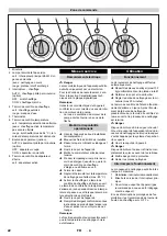
1 Time switch
2 Control lamp operating state
green: Emergency-stop switch turned on
yellow: Cleaning process active
red: Turntable overloaded
3 Heating switch
AUTO: Heater is controlled via the timer
(option)
OFF: Heater off
1/ON: Heater on
4 Indicator lamp - heater
green: Heater released
red: Water shortage
5 Temperature controller
6 Temperature indicator lamp
green: selected temperature reached
yellow: Heater active, selected temper-
ature not reached yet
red: Over temperature (more than 94
°C) temperature limiter was triggered
7 Skimmer switch (option)
AUTO: Skimmer is controlled via the
timer (option)
OFF: Skimmer has been switched off
1/ON: Skimmer is switched on
8 Indicator lamp, skimmer
green: Skimmer is active
Danger
The electrical connection of the system
may only be carried out by a qualified elec-
trician.
For connection values, see technical data
and type plate.
Note
After connecting the device to the power
supply, check the rotating direction of the
pump motor to see it is running in right di-
rection.
–
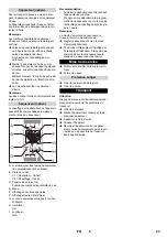
The fan of the pump motor must rotate
in the direction of the arrow.
Î
Align the appliance horizontally at the
installation site.
Î
Lock the brakes of the steering rollers.
Î
Ensure that the drain-off tap is closed.
Î
Open the device hood.
Î
Turn on the main switch.
Î
First-time filling: Fill in water into the de-
tergent container until the indicator
lamp "Heater" goes off or lights up
green.
Î
Close cover.
Î
Set the thermostat to the desired clean-
ing temperature (max. 80°C).
Î
Switch on the heating. Heater indicator
lamp glows green.
The indicator lamp for the temperature
lights up yellow during the heating process
and changes to green when the selected
temperature is reached.
Î
Open the device hood.
Î
Add detergent to the detergent contain-
er according to the instructions given in
the product information and start a short
cleaning cycle.
Note
The device can be operated even before
the selected cleaning temperature has
been reached.
The cleaning process takes place in a fully
automatic mode.
Î
Distribute the parts to be cleaned (max.
130 kg) evenly on the turntable.
Î
Close and lock the appliance cover.
Î
Set the cleaning time at the timer (max.
30 minutes).
The indicator lamp "Operating Status" will
light up yellow. The indicator lamp of the
operating status switches to green at the
end of the selected cleaning period; the
cleaning process is completed.
Danger
Danger of scalding by hot steam! Do not
open the machine hood at the end of the
cleaning process until the steam has es-
caped through the steam exhaust.
Î
Open the device hood.
Danger
Risk of burns! Allow cleaned parts to cool
down adequately before removing them.
Î
Wear safety gloves.
Î
Remove the cleaned parts.
The cleaning process can be interrupted in
3 different ways.
1 Reset timer manually.
2 Switch off the main switch.
3 Open the machine hood (not recom-
mended due to heavy steam).
During longer non-use of the machine it
makes sense to turn the heater switch to
"OFF".
The machine is fitted with a skimmer to in-
crease the life of the detergent fluid.
The skimmer transports oil floating on the
detergent liquid to the oil catch container.
Note
Best results of the skimmer can be reached
when the detergent liquid is cold.
Î
Let the detergent liquid cool down for at
least one hour so that the oil can sepa-
rate from the water.
Am besten vor Arbeitsbeginn durch-
führen.
Î
Switch on the skimmer - once a day for
a few minutes depending on the oil ap-
plication.
Best time: In the morning prior to start of
work, in cooled, calm condition.
Î
Also empty the oil collection basin.
Note
Please dispose off the collected oil accord-
ing to the regulations.
Operating field
Start up
Power connection
Making the plant ready for
operations
Operation
Operation
Interrupting operation
Skimmer (option)
14
EN
Summary of Contents for PC 60T
Page 2: ...2...
Page 92: ...2 0 15 Ohm 3 92 EL...
Page 93: ...3 1 2 3 4 5 6 7 8 9 10 11 12 13 14 15 16 17 18 Not Aus 19 20 21 22 93 EL...
Page 94: ...4 1 2 3 AUTO OFF 1 ON 4 5 6 94 C 7 AUTO OFF 1 ON 8 80 C 130 kg 30 3 1 2 3 OFF 94 EL...
Page 95: ...5 Am besten vor Arbeitsbeginn durchf hren 1 A 5 B C1 1 C2 2 C D E F G 1 2 H I 1 95 EL...
Page 96: ...6 1 K rcher 40 200 1000 96 EL...
Page 97: ...7 0 97 EL...
Page 108: ...2 0 15 BGV A3 108 RU...
Page 109: ...3 1 2 3 4 5 6 7 8 9 10 11 12 13 14 15 16 17 18 19 20 21 22 109 RU...
Page 110: ...4 1 2 3 OFF 1 ON 1 4 5 6 94 C 7 OFF 1 ON 1 8 80 C 130 30 1 2 3 OFF 110 RU...
Page 111: ...5 Am besten vor Arbeitsbeginn durchf hren 1 A 5 B C1 1 C2 2 C D E F G 1 2 H I 1 111 RU...
Page 112: ...6 1 Karcher 40 200 1000 112 RU...
Page 113: ...7 0 113 RU...
Page 180: ...2 30 mA IEC 60364 1 0 15 Ohm BGV A3 180 BG...
Page 181: ...3 1 2 3 4 5 6 7 8 9 10 11 12 13 14 15 16 17 18 19 20 21 22 181 BG...
Page 182: ...4 1 2 3 AUTO OFF 1 ON 4 5 6 94 C 7 AUTO OFF 1 ON 8 80 C 130 30 3 1 2 3 OFF 182 BG...
Page 183: ...5 Am besten vor Arbeitsbeginn durchf hren A 5 B C1 1 C2 2 C OK D E F G 1 2 H I 1 T o 183 BG...
Page 184: ...6 1 K rcher 40 200 1000 184 BG...
Page 185: ...7 0 185 BG...
Page 212: ...2 0 15 BGV A3 212 UK...
Page 213: ...3 1 2 3 4 5 6 7 8 9 10 11 12 13 14 15 16 17 18 19 20 21 22 213 UK...
Page 214: ...4 1 2 3 OFF 1 ON 1 4 5 6 94 C 7 OFF 1 ON 1 8 80 C 115 30 3 1 2 3 OFF 214 UK...
Page 215: ...5 Am besten vor Arbeitsbeginn durchf hren A 5 B C1 1 C2 2 C OK D E F G 1 2 H I 1 215 UK...
Page 216: ...6 1 K rcher 40 200 1000 216 UK...
Page 217: ...7 0 217 UK...
Page 219: ......


