


INSTALLATION INSTRUCTIONS
We recommend installation by a specialist workshop. A lifting platform is also useful for attaching contact brushes in deep-set entry points.
If you have any technical questions, please contact us at
SAFETY INFORMATION
•
WARNING: HIGH-VOLTAGE!
High voltage is not harmful to healthy persons. You should, however, avoid contact with the contact brushes.
This applies in particular to people with heart disease or heart pacemakers.
• We can only guarantee the full functioning of the device when it is used with 4 AA (each 1.5 V) batteries (not rechargeable batteries).
• Always protect the marten repellent device against excessive heat and prevent or eliminate dirt on the contact brushes.
• Always comply with the working steps in these installation instructions and the safety information.
• Damage caused by not observing the installation instructions is excluded from any liability.
•
Clean the engine compartment and parking space thoroughly before installation in order to avoid turf wars (we recommend the K&K scent mark remover for the engine
compartment, item 000300) (15).
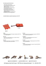
Intended use:
The device is used to expel martens and other wild animals from the vehicle engine compartment by means of electric shock, pulsating light and aggressive, pulsating ultrasound
frequencies. After the marten has triggered a short circuit, the high-voltage function is switched off for a short time in order to give the animal the opportunity to escape.
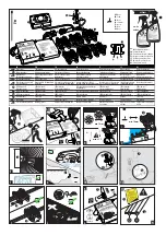
FUNCTION TEST
prior to installation
All devices are carefully checked by us multiple times. Please also carry out the following final checks:
1) Ensure that the toggle switch is in the “OFF” position
(A)
.
2) Place the contact brush
(3)
at the end of the cable
(4)
, insert screws into the high-voltage cable
(J)
and lay on insulated underlay (cardboard, wood).
3) Place the batteries in the control device, 4 x AA
(A1)
.
4) Switch the toggle switch to the “ON” position
(K)
.
5) Don’t touch the contact brush (high voltage) and control device (vibration) any more.
6) LED
(6 + 7 + 8)
flashes to indicate it is working. This can take a few minutes and take place at a later time
(L)
.
7) High voltage can also be measured using a digital multimeter on the positive cable of the contact brush
(N)
.
8) Pull multi-pin plug
(9)
to immediately cut off the current or Set toggle switch to “OFF”
(A)
. (WARNING! After removal, contact brush will carry approx. 3 minutes of residual current)
9) End of function test
Info:
Warranty is exclusively for the device. There is no assumption of assembly and disassembly costs! Complete dismantling is rarely required - control unit can be exchanged!
INSTALLATION
with the multi-pin plug unplugged, toggle switch set to “OFF”
CONTROL UNIT
Mount the control unit
(1)
in a place where it cannot overheat (e.g. not directly on the exhaust manifold)
(B)
. Observe the manufacturer’s operating temperature regarding the batteries.
The LEDs
(6 + 7 + 8)
should be visible and the battery compartment should be easily accessible.
ULTRASOUND TRANSMITTER
Mount the ultrasound transmitter
(2)
in a place where it cannot overheat
(B)
and the ultrasound can radiate as freely as possible in order to avoid acoustic shadow
(E)
. Fully sealed, waterproof
electronics in accordance with the IP 65 standard and a fully enclosed speaker allow the device to be installed low down, including in areas where there may be splashing water and the entry area
of the martens. Withstands even engine washing.
CONTACT PLATES
Raise the contact brushes
(3)
onto the high-voltage cable
(4)
and lay this in a strategic location in the engine compartment. Contact brush positions should be adapted to the conditions of the
engine compartment (secure entry points, routes and bite-endangered areas)
(G)
. The high-voltage cable should not be placed anywhere near hot and/or rotating engine parts
(B)
. Contact
brushes should be mounted at a minimum distance of 10mm to other conductive parts (short-circuit hazard)
(C)
and at an angle (water drainage)
(D)
. Attach the contact plates with cable ties
(I)
.
Tightening the screws fixes the contact plate, ‘taps’ the high-voltage cable and makes contact
(J)
. The end of the cable should not protrude from the last contact plate due to a short-circuit hazard.
Please attach the yellow warning sticker ‘Warning high voltage’ (11) so it can be clearly seen in the engine compartment (K)!
BONNET SWITCH
The bonnet switch
(5)
prevents the possibility of a voltage build-up when the bonnet is open.
During the assembly, make sure that the eyelet
(12)
is placed under the fastening bracket and tightened with the fixing screw
(13)
so that it can allow electrical conduction with the contacting
surface under the mounting bracket of the switch. The 6.3 mm male terminal
(14)
is plugged into the lower contact tab of the switch
(H2)
.
INITIAL OPERATION
Set the toggle switch to the “ON” position
(K)
. The control LED for the ultrasound function
(6)
will start to flash (approx. every 3-12 seconds). When the bonnet is opened, the bonnet switch cuts
out the high-voltage function. To test the function, press the bonnet switch down and wait for the control LED for the high-voltage function
(7)
to blink. This procedure may take a few minutes
when operating for the first time
(L)
. In this state, do not touch the contact brushes or the control device. The bonnet switch is working properly when the high-voltage LED goes out when you let
go. The LEDs for function control can flash at various distances and at different degrees of brightness.
BATTERIES
The battery life lasts approx. to 12 months. If the Battery Low LED
(8)
starts to flash, there is still approx. 3 to 4 weeks left to replace the batteries.
Only use AA batteries with 1.5 V voltage, not rechargeable batteries. If standard rechargeable batteries with 1.2 V voltage are used,
the required operating voltage will not be reached. If modern rechargeable batteries with 1.5 V voltage are used, the display for the
battery status will not work, as these batteries discharge abruptly, not slowly like AA batteries.
The M9700 is a highly efficient high-voltage defence solution.
Despite this, we cannot guarantee that the martens will be expelled in 100% of all cases.
MORE INFORMATION
If the device does not work, it could be for the following reasons:
1) The batteries are not properly placed or are too weak.
2) The contact brushes are touching other conductive parts (short circuit)
(C)
.
3) Contacts in the connector
(9)
to the basic device have no connection (not correctly inserted, pin is bent).
4) There is a delay of several seconds when switching on. Have patience
(M)
!
5) The toggle switch is not set to “ON”.
6) The bonnet switch is not in the pressed-down position.
7) Automatic shut-off is active via vibration with quick LED
(6)
flashes.
Disposal:
Dispose of the device and batteries in conformance with national regulations.
Accessories
- Extension Kit with 4 additional high voltage contact brushes No M9700-KIT - Replacement control unit No M9700-ST
Technical data:
• Operating voltage: 6 V, 4 AA batteries
• battery life: to 12 months
• Average power consumption: approx. 0,2 mA
• Ultrasound frequency: approx. 20 - 25 kHZ pulsating
in frequency and cycle, SINUSOIDAL
• Sound pressure: approx. 110 dB (+/- 20%)
• High voltage: > 250 V
• Operating temperature range: approx. -25°C to +80°C
• Function display: 3 Flashing LEDs for high voltage (slowly flashing),
ultrasound/vibration (slowly flashing / fast flashing),
battery (slowly flashing, if the battery is weak)
• Dimensions control device: approx. 155 x 88 x 32 mm
• high-voltage cable length: approx. 4 m
• Dimensions loudspeaker: 84 x 54 x 44 mm
• cable length to the loudspeaker: approx. 1.5 m
• Multi-contact high-voltage brushes with plus and minus strands
• Also suitable for vehicles with CAN bus.
Automatic reduction of power consumption in the case of short-circuit or
contamination (reactive currents) at the high-voltage brushes. Compact
plug-and-socket connection at control device for simple disconnection of
the control device from the cable installation.
Licensed with the e1
symbol by the German Federal Motor Transport Authority.


