


Installation and Operation Manual
0150-0133
4-4
Revision B
4.3.2 RS-485 Network Connector Wiring
RS-485 Connections
Front View of Keyboard Input Jacks
Pin 1 or 7:
Gnd (shield)
Pin 3:
+
ve
Pin 6:
-
ve
The remaining pins are not used.
1 2 3 4 5 6 7 8
Table 4-2. RS-485 Connections.
4.4 The RS-422 Network
The RS-422 network is a multi-drop, wiring configuration, with a maximum length of 3,000 feet (1,000
meters). RS-422 connectors are used for most hookups (see system diagram on page 4-1). Some
equipment may use flying leads or terminal blocks. If this is the first or last device on the network,
terminate the device with a 100-ohm terminator plug. (Usually available from unit supplier.) Most
Kalatel units have looping RS-422 network connectors, meaning that the signal is looped in and out of
the unit on the same connector.
4.4.1 RS-422 Connections and Cabling
RS-422 Cable Specification
#22 AWG, Twisted Pair, unshielded (2-wire)
Less than 25-ohm per 100 foot, nominal
2-wire: Belden 8442 or 8740 (unshielded)
Table 4-3. RS-422 Cable Specification.
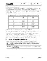
4.4.2 RS-422 Network Connector Wiring
RS-422 Connections
Front View of Keyboard Input Jacks
Pin 1:
A
, (
+ voltage
)
Pin 2:
B
, (
- voltage
)
The remaining pins are not used.
1 2 3 4 5 6 7 8
Table 4-4. RS-422 Connections.
Summary of Contents for CBR-KB3
Page 4: ...Installation and Operation Manual 0150 0133 iv Revision B This page intentionally left blank ...
Page 6: ...Installation and Operation Manual 0150 0133 vi Revision B This page intentionally left blank ...
Page 10: ...Installation and Operation Manual 0150 0133 1 4 Revision B This page intentionally left blank ...
Page 12: ...Installation and Operation Manual 0150 0133 2 2 Revision B This page intentionally left blank ...
Page 37: ...Installation and Operation Manual Revision B 7 3 0150 0133 ...


