


Installation and Operation Manual
Revision B
4-3
0150-0133
4.2 Start-Up
Supply power to the CBR-KB3 using the 110-240 VAC to 12 VDC adapter.
Test the operation of the CBR-KB3 to verify the integrity of the connections and that it operates in a
correct manner as follows (For front panel controls, refer to the pages preceding this section.)
Connect the CBR-KB3 keypad to the multiplexer using a RJ-45 to RJ-45 adapter cable, as illustrated
above. This cable should contain only two wires for the
TX
and
RX
signals. Follow the shield
grounding requirements described below.
Power up the unit as described above. Ensure that all network connections are made before powering
on.
A self-test lights all the LEDs, and a buzzer sounds. The firmware version and model number is briefly
displayed on the keyboard LCD display.
The CBR-KB3 then polls the network. It uses the results to set its own network address, and to allow
connection to other multiplexers. After this point, a manual poll can also be done at any time.
Change the automatic keyboard network address if a specific network address is required.
The CBR-KB3 connects to the first available multiplexer on the network. for additional information on
how to interpret the polling results displayed in the LCD readout, see section 5.
4.3 The RS-485 Network
The RS-485 network is a multi-drop, wiring configuration, with a maximum length of 3,000 feet or
1,000 meters (without signal amplification or modems). RJ-45 connectors are used for most hookups
(see the system diagrams starting on page 4-1). A 100-ohm terminator is required at each end of the
RS-485 line. Some equipment may use flying leads or terminal blocks.
Most Kalatel units have looping RS-485 network connectors. Either socket can be used.
NOTES:
Do not use
third party RS-485 equipment without first consulting Kalatel
Technical Support for information on compatibility with Kalatel equipment.
4.3.1 RS-485 Connections and Cabling
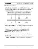
RS-485 Wire Specification
#24 AWG, twisted pair with shield (2-wire)
Less than 16 pF per foot, nominal
Less than 25 ohms per 100 foot, nominal
2-wire: Belden 9841 (shielded)
4-wire: Belden 9842 (shielded)
Table 4-1. RS-485 Wire Specification.
Connecting the shields on the RS-485 lines.
Shields should be connected on one end of the cable run only, and where possible, grounded to the
multiplexer end of the cable. When a cable run is between two multiplexers or two keyboards, select
either the multiplexer or the keyboard (but only one, not both) to provide the termination.
If the cable run is between a keyboard and a ProBridge, then the shield should be connected to the
keyboard end.
Summary of Contents for CBR-KB3
Page 4: ...Installation and Operation Manual 0150 0133 iv Revision B This page intentionally left blank ...
Page 6: ...Installation and Operation Manual 0150 0133 vi Revision B This page intentionally left blank ...
Page 10: ...Installation and Operation Manual 0150 0133 1 4 Revision B This page intentionally left blank ...
Page 12: ...Installation and Operation Manual 0150 0133 2 2 Revision B This page intentionally left blank ...
Page 37: ...Installation and Operation Manual Revision B 7 3 0150 0133 ...


