Installation and Operation Manual
Revision B
4-1
0150-0133
4
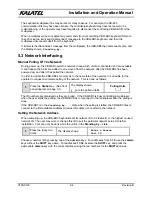
W
IRING AND
C
ONNECTIONS
The following diagram shows the wiring configuration when connected to Kalatel telemetry equipment. A
Calibur ProBridge is required when connected to selected other manufacturers equipment, Wiring and
operation for these other devices is discussed in the specific ProBridge manual for that manufacturer.
4.1 System Wiring Diagrams
RJ-45 Connectors
12Vdc
power
adapter
12Vdc
power
adapter
CBR-KB3
Kalatel
Mini-Dome
Calibur CBR, MMX and DVMR
series video equipment
12Vdc power
adapter
24Vac
power
adapter
1
2
3
4
5
6
7
8
9
10
11
12
13
14
15
16
RS-232
1 RS-485 2
12V DC
B
2-wire twisted
unshielded
BLK
RED
Interface
Connector
Card
(Supplied)
RJ-45 Connector
12V DC
RS-422
1 PWR 2
RS-485
12V DC
RS-422
1 PWR 2
RS-485
RS-422 Cable:
RJ-45 to RJ-45
(Supplied)
WHT/
GRY
BRN
YEL
GRN
BLK
ORG
BLU
red
blk
8
7
6
5
1
2
3
4
Remote Keypad
2-wire twisted
unshielded
RS-485 Cables:
RJ-45 to RJ-45
(Supplied)
CBR-KB3/J
RED
14 Vdc POS (+)
DTMF-A
Terminal
RS-422 (Out B)
RS-422 (IN A)
Kalatel
Terminal Block Wiring
RS-422 (IN B)
RS-422 (Out A)
14 Vdc NEG (-)
DTMF-B
Signal
8
7
6
5
1
2
3
4
Terminal Block
(Supplied)
(Supplied)
Remote Keypad
(Supplied)
Configuration Note:
This wiring method should be used when no
other KTD series equipment will be used in the
system.
Video Signal
Coaxial Cable
Non-Digiplex Applications
Summary of Contents for CBR-KB3
Page 4: ...Installation and Operation Manual 0150 0133 iv Revision B This page intentionally left blank ...
Page 6: ...Installation and Operation Manual 0150 0133 vi Revision B This page intentionally left blank ...
Page 10: ...Installation and Operation Manual 0150 0133 1 4 Revision B This page intentionally left blank ...
Page 12: ...Installation and Operation Manual 0150 0133 2 2 Revision B This page intentionally left blank ...
Page 37: ...Installation and Operation Manual Revision B 7 3 0150 0133 ...


