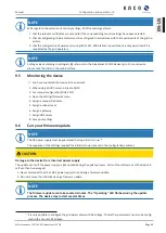
If the applicable grid code stipulates that the reactive power should react to the target value slower than the
configured Tau=200 ms by way of a defined gradient or settling time, this gradient or settling time must be im-
plemented in the system control.
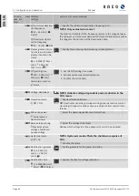
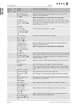
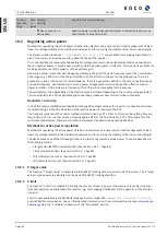
Parameter
Setting
Refer-
ence
Description
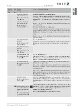
Q constant
[VArWMaxPct]
0-100 [%
Slim
]
Setpoint of the reactive power can be ad-
justed depending on the set maximum ap-
parent power.
Increasing output gradient
&
Decreasing output gradi-
ent
[VArPct_RmpTms]
1 – 65524 [% Slim / min]
Determines the dynamic behaviour in the
event of a change in the reactive power
value. The reactive power is changed with
the specified gradient.
Note: The gradient is overlaid with the set-
tling time.
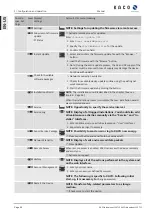
Settling time
[
VArPct_WinTms]
200 – 60000 [ms]
Determines the dynamic behaviour in the
event of a change in the active power/reac-
tive power set value. The active power/re-
active power is changed according to a PT-1
characteristic curve with a settling time of 5
Tau.
NOTE: The settling time is overlaid
with the increasing and decreasing
gradient.
Timeout
[
VArPcT_RvrtTms]
0 – 1000 [s]
Sets the time after which the inverter, if it
does not receive a new reactive power
specification, falls back to the previously
valid reactive power procedure.
If the
Timeout
is set to
0
seconds, the
transmitted power factor specification is
permanently retained, even in the event of
a communication failure.
Note: when the unit is restarted, the
Timeout
is reset to the set fallback time.
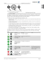
cos φ(P)
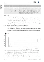
In the cos ϕ (Pn) operating mode, the setpoint value of cos ϕ and the setpoint for the reactive power derived
from it are continuously calculated depending on the actual power level. This function ensures that grid sup-
port is provided by the reactive power when a significant voltage boost is anticipated due to a high feed level.
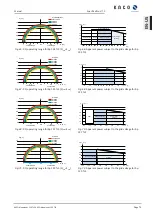
In this case, a characteristic curve is specified which can be used to configure up to 10 nodes, value pairs for ac-
tive power and cos ϕ. The active power is entered as a % in relation to the set maximum apparent power Slim.
Other parameters allow you to limit functionality and to limit activation to certain voltage ranges.
S
lim
Fig. 81:
cos ϕ (P) standard characteristic curve with 3 nodes
10 | Specifications
Manual
KACO blueplanet 110 TL3 KACO blueplanet 125 TL3
Page 78
EN-US

