20
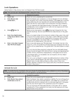
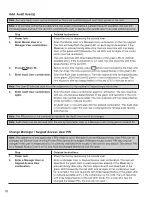
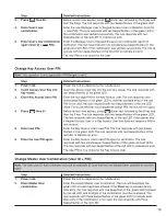
Step
Detailed Instructions
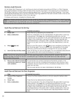
3.
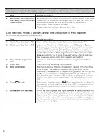
Press then 50.
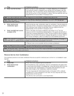
Before re-lock time expires, press (Enter key) followed by the 5 key and
then the 0 key. The lock re sponds with two beeps/flashes of the green LED.
4.
Enter new Master User
Enter a new Master User combination. The lock re sponds with two simulta-
neous beeps/flashes of the green LED if the User ID portion of the combina-
tion is unique. The lock re sponds with two beeps/flashes of the red LED to
indicate an error.
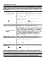
Note: The User ID selected must be in the range from 0 to the number of keypad users minus one.
Note: When PIN length = 0, Combination = User ID only; otherwise , Combination = User ID + PIN.
5.
Enter new Master User
Enter the new Master User combination again for ver i fi ca tion. The lock
com bi na tion again.
responds with two si mul ta neous beeps/flashes of the green and red LEDs if
the com bi na tion was verified successfully.
The lock re sponds with two beeps/flashes of the red LED to indicate an error.
The new combination is now active for the Master User.
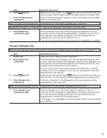
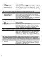
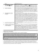
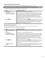
Open the Lock with Combination
Step
Detailed Instructions
1.
Power lock.
Power the lock by depressing the outside lever.
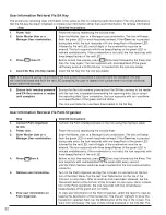
2.
Enter combination.
Enter the combination to open the lock. The lock will beep/flash the green
LED on each key stroke entered. If the Clear key is pressed during data
entry, the lock responds with one beep/flash of the green LED followed by
the red LED, and all digits of the combination must be re-entered.
Caution: When opening the lock, do not depress the outside lever until the lock responds with three beeps/flashes
of the green LED to indicate available entry.
The lock responds with three beeps/flashes of the green LED to indicate
available entry. If the combination is that of an Keypad Access User or
Service User and the User ID has been disabled by managerial personnel,
the lock responds with two beeps/flashes of the red LED. If the com bi na tion
is not valid, the lock responds with three beeps/flashes of the red LED.
Note: After the limit of consecutive failed entry attempts has been reached, the lock will tem po rari ly shut down to
prevent com bi na tion tam per ing for the time programmed by managerial personnel. During the shut down period,
the lock will not respond to any user actions. When the shutdown period has elapsed the lock can be used nor mal ly.
Any additional failed entry attempt results in the lock being disabled again for the pro grammed shut down time. This
cycle will continue until a correct com bi na tion is entered.
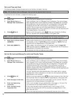
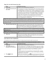
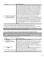
3.
Open lock.
Before re-lock time expires, depress the outside lever to open the lock. At
the end of the re-lock interval the lock will respond with two simultaneous
beep/flashes of the red and green LEDs.
Summary of Contents for PowerLever 455 Series
Page 1: ...PowerLever 455x Operating Instructions...
Page 37: ...37 Notes...
Page 38: ...38 Notes...
Page 39: ...39 Notes...

