14
Lock Operations
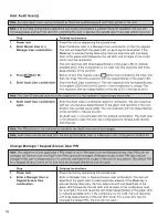
Define Number of Key Access Users and Keypad User PIN Field Length
Note: The lock must be in the Shelved mode to select this menu.
Step
Detailed Instructions
1.
Power lock.
Power the lock by depressing the outside lever.
2.
Enter Master User
Enter the Master User combination on the lock keypad. The lock will beep/
combination.
flash the green LED on each keystroke entered. (If the Clear key is pressed
during data entry, the lock responds with one alternate beep/flash of the
green and red LED, and all digits of the combination must be re-entered.)
The lock responds with three beeps/flashes of the green LED to indicate
available entry. If the com bi na tion is not valid, the lock responds with three
beeps/flashes of the red LED.
3.
Press then 15.
Before re-lock time expires, press (Enter key) followed by the 1 key
and then the 5 key. The lock responds with two beeps/flashes of the green
LED.
4.
Enter Four-Digit Number
Enter a four-digit number for the maximum number of Key users to be used
of Key Users (Refer to table
in the lock. This number must be in the range of 0000–2995 and a multiple
of p. 5.)
of 5. The lock re sponds with two beep/flashes of the green LED if the data
entered is ac cept able. If the entered data is not acceptable, the lock re -
sponds with two beep/flashes of the red LED.
5.
Enter a One-Digit Keypad
Enter a one-digit keypad user PIN field length. This number must be in the
User PIN Field Length.
range of 0–4. For a lock that has not been pre vi ous ly configured, the lock re -
sponds with two beep/flashes of the green LED if the data entered is accept-
able.
For a lock that has been previously configured, the lock alternately beeps/
flashes the red and green LEDs while the lock is being reconfigured and ter-
minates with two si mul ta neous beeps/flashes of the green and red LEDs.
If the entered data is not ac cept able, the lock responds with two beeps/
flashes of the red LED.
The lock is now configured to support the defined maximum number of Key
Users and the defined Keypad User PIN length. The maximum number of
Keypad Users has also been set based on the number of Key Users
defined. (Num ber of Keypad Users equals 3000 minus the defined maximum
number of Key Users.)
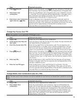
Activate the Lock
Note: To activate the lock, the Master User must change the default Master User combination of all 0’s. The default
combination must be changed before any lock operations can be performed.
Step
Detailed Instructions
1.
Power lock.
Power the lock by depressing the outside lever.
2.
Enter Master User default
Enter the Master User default combination of all 0’s. The lock will beep/flash
com bi na tion of all 0’s.
the green LED on each keystroke entered. (If the Clear key is pressed dur-
ing data entry, the lock re sponds with one alternate beep/flash of the green
and red LED, and all digits of the combination must be re-entered.)
The lock re sponds with three beeps/flashes of the green LED to indicate
available entry. If the com bi na tion is not valid, the lock responds with three
beeps/flashes of the red LED.
Summary of Contents for PowerLever 455 Series
Page 1: ...PowerLever 455x Operating Instructions...
Page 37: ...37 Notes...
Page 38: ...38 Notes...
Page 39: ...39 Notes...


