background image

1 8

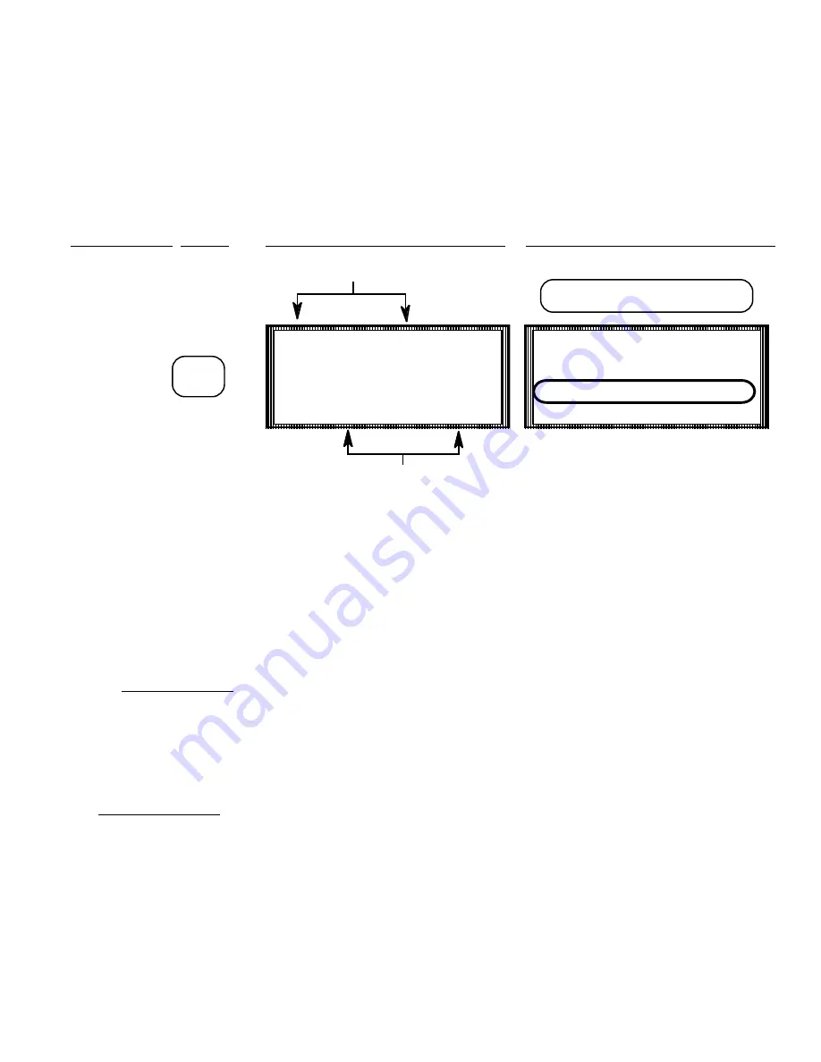
PRODUCT NAMES AND SPECIFIC GRAVITY

TO  PROGRAM  PRESS

  MULTI-TANK  SCREEN  DISPLAYS     SINGLE-TANK SCREEN DISPLAYS

To change product names and / or specific gravities press the 

<PROD>

 pushbutton from the Multi-tank

display and the above display will appear (the product name and specific gravity always appears on the

single tank display).  Press the

 <PROG>

 pushbutton to alert the system that the programming function is

desired and activate the keypad. 


 On the Multi-tank  display a flashing number appears at the bottom center of the display which signifies

the tank channel number from the list above for which, if entered, the product will be changed.  If a

different tank product is to be changed other than that which is indicated by the flashing number,  select

the desired channel number from the keypad and press 

<ENTER>. 

The Single tank screen  displays the product name and specific gravity as part of the normal readout.  If the

product name to be changed is for a tank other than what is currently being displayed, use the

 <UP-

DOWN scroll arrows> 

on the left of the display to move to the desired tank.  When the proper tank is

displayed press the

 <PROD>

 button.

The following screen will appear when the 

<PROD>

 button from the single tank display or the 

<ENTER>

button from the Multi-tank display is pressed:

PROD

  1  WHEY      5  SKIM
  2  MILK       6  OIL        
  3  WATER    7  SUCRSE
  4  CREAM    8  JUICE

CHANNEL NUMBER

PRODUCT NAME

TANK 1   42730   GAL.
CH:  1    **HI**   LEVEL
CREAM    0.998    SPGR
            97% FULL

PRODUCT NAME AND SPECIFIC 
GRAVITY ALWAYS DISPLAYED

Summary of Contents for K1600

Page 1: ...NITS OF MEASURE 5 D PRODUCT NAMES 6 E SPECIFIC GRAVITY 6 F PERCENT FULL 6 G GENERAL ALARM STATUS LINE 6 H LEVEL ALARM STATUS 7 I ANALOG TO DIGITAL COUNTS 7 J TRANSMITTER ZERO OFFSET MANUAL AUTO ZERO FUNCTION III VIEWING DATA A UNITS 9 B PRODUCT IN TANKS 9 C ALARM SETPOINTS HI MID LOW 1 0 D ZERO OFFSET VALUES 1 1 E TIME DATE 1 1 F INVENTORY SCREENS 1 1 8500 Installation Start up Operation Lit 8500 ...

Page 2: ...FFSETS 2 2 UNITS OF MEASURE SETTING 2 6 V INSTALLATION AND START UP INSTALLATION OF INVENTORY CABINETS 2 8 4 20 MA TRANSMITTERS 2 9 4 20 MA SIGNAL LINES 2 9 PNEUMATIC TANK SENSORS 3 0 PNEUMATIC SIGNAL LINES 3 0 LEVEL ALARM OUTPUTS 3 1 RS232 COMMUNICATIONS 3 1 OPERATION AND START UP 3 1 INSTALLATION AND START UP SUMMARY 3 3 SENSOR MISC INSTALLATION DOCUMENTS ...

Page 3: ...round even while the operator has control of the system through the LCD display and the front panel key pad The K1600 can be configured to accept up to 16 pneumatic or 4 20 milliamp input signals from the sensors in the tank This signal is converted from analog to digital ATOD counts which in conjunction with the entered specific gravity and programmed tank profile tables are utilized in determini...

Page 4: ...own arrow keys In addition inventory can be read in POUNDS or GALLONS LITERS or KILOGRAMS by selecting the UNITS button Optional field programmable alarm outputs an RS232 communication port and Printout capability allow accurate inventory information to be brought out to a host of peripheral devices for reporting and control Although the K1600 Tank Inventory System is micro processor based it is f...

Page 5: ...and LO L level values The single tank screen will display the HIGH MID LO for the tank selected Press RUN PAGE to return to normal inventory display PROD changes screen to view product names for all tanks from the multi tank screen Product names are normally displayed on the single tank screen TIME changes Multi tank screen to view the zero offset values in ATOD counts of the ZERO transmitter outp...

Page 6: ...ntories are continuously updated the operator can easily toggle from Page 1 to Page 2 by using the scroll keys The PAGE key can be used to toggle from the Multi tank display to the Individual tank display where more complete tank information can be viewed 1 40345 G 5 M 789 2 L 567 6 3705 3 456 7 26536 4 E 67 8 1789 TANK LEVEL STATUS OUTPUT E SENSOR NONE L OR BELOW LO SETPOINT ON ABOVE LO BELOW MID...

Page 7: ...used to toggle between the multiple and individual tank screens PAST 1 13732 GAL CH 2 Hi LEVEL CREAM 0 998 SPGR 97 FULL PERCENT FULL OF TANK VOLUME BASED ON EMPTY TO HI LEVEL SETPOINT PRODUCT NAME AS SELECTED FROM PRODUCT LIST PRODUCT SPECIFIC GRAVITY AS SELECTED ORENTEREDFROM PRODUCT LIST TANK NAME AS PROGRAMMED INVENTORY VALUE IN UNITS SELECTED UNITS SELECTED LEVEL ALARM STATUS HI MID LO CHANNEL...

Page 8: ...decremented using the scroll keys TANK NAMES Tank names or designations which define a particular tank appear in the upper left hand corner of the single tank display and consist of up to six characters Names such as RT 1 PT 6 or TANK 3 help the operator identify a tank Tank Names are supplied by the customer and are entered into the system prior to shipment as part of the initial factory set up T...

Page 9: ...ffects the head pressure being measured The specific gravity of the product displayed has a direct effect on the accuracy of the inventory value and as such care should be taken to insure that the proper SPGR is shown Even though the product name is correct incorrect SPGR can adversely effect the inventory value indicated The correct specific gravity for a product is entered and linked to the prod...

Page 10: ... preceding the word LEVEL When the tank product level is at or above the Hi level setpoint the characters HI appear Similarly when the product level is at or above the Mid level setpoint and below the Hi level setpoint the characters Md appear The characters OK are displayed when the product level is betweem the lo level and the mid level setpoints LO appears when the level is at or below the lo l...

Page 11: ...a with a corresponding Zero Offset AtoD value of approximately 50 counts The Zero Offset value for a particular tank can be viewed by pressing the TIME ZERO button when in the Single tank display mode and verified by comparing it to the actual AtoD count currently being converted from the level sensor when the tank is empty Both ATOD values should be identical If they are not corrections can be pr...

Page 12: ...hanged from either display mode are UNITS OF MEASURE PRODUCT NAMES AND SPECIFIC GRAVITIES ALARM LEVEL SETPOINTS TRANSMITTER ZERO OFFSET VALUES TIME AND DATE TO VIEW PRESS MULTI TANK SCREEN DISPLAYS SINGLE TANK SCREEN DISPLAYS UNITS N A Ô PRODUCT IN TANKS PROD 1 WHEY 5 SKIM 2 MILK 6 OIL 3 WATER 7 SUCRSE 4 CREAM 8 JUICE CHANNEL NUMBER PRODUCT NAME TANK 1 42730 GAL CH 1 HI LEVEL CREAM 0 998 SPGR 97 F...

Page 13: ...SETPOINT 1M 1500 MD 5M1000 2M 2500 GA 6M1000 3M 5000 7M1500 4M 3900 8M1450 CHANNEL NUMBER MID LEVEL SETPOINT TANK 1 ALARMS CH 1 LO LEVEL 100 GALS MD LEVEL 1500 GALS HI LEVEL 4000 GALS 1L100 LO 5L 500 2L 250 Ga 6L 500 3L 250 7L 650 4L 300 8L 245 CHANNEL NUMBER LO LEVEL SETPOINT TANK 1 ALARMS CH 1 LO LEVEL 100 GALS MD LEVEL 1500 GALS HI LEVEL 4000 GALS TANK 1 ALARMS CH 1 LO LEVEL 100 GALS MD LEVEL 1...

Page 14: ...9 NEW TIME 08 47 15 NEW DATE 09 15 89 tz TO SET TIME DATE 1 42730 G 5M 789 2L 567 6 3705 3 456 7 26536 4E 300 8 1789 CHANNEL NUMBER INVENTORY VALUES TIME ZERO TANK 1 42730 GAL CH 1 HI LEVEL CREAM 0 998 SPGR ZERO 50 ATOD 3467 XMTR ZERO IN ATOD COUNTS XMTR READING IN ATOD COUNTS TIME ZERO TIME ZERO 08 47 15 09 15 89 NEW TIME 08 47 15 NEW DATE 09 15 89 tz TO SET TIME DATE TANK 1 42730 GAL CH 1 HI LEV...

Page 15: ... the page or moves to the next screen and terminates the programming mode ACCESSCODES The system recognizes three codes that allow access to restricted programming areas These three unique codes are programmed through the system and correspond to three levels of clearance Low High and Master The Master access code is reserved for areas in the system which are used to initially set up the system pa...

Page 16: ...ND DATE TO PROGRAM PRESS MULTI TANK SCREEN DISPLAYS SINGLE TANK SCREEN DISPLAYS TIME DATE Press the TIME ZERO button twice from either the Multi tank or Single tank display Then press the PROG button to activate the programming feature The screen displays access code Enter the low level access code If a mistake is made the following screen will be displayed and the sequence will have to be restart...

Page 17: ...nged The cursor will move to the next field when ENTER is pressed 2 When the desired time and date appear turn off the programming feature by pressing the PROG button again 3 Press the TIME ZERO button to enter the changes into the system The top line will now display the new time and date 4 Press the RUN PAGE button to return to the inventory screen ERROR YOUR ACCESS LEVEL IS NOT HIGH ENOUGH FOR ...

Page 18: ...a different tank product is to be changed other than that which is indicated by the flashing number select the desired channel number from the keypad and press ENTER The Single tank screen displays the product name and specific gravity as part of the normal readout If the product name to be changed is for a tank other than what is currently being displayed use the UP DOWN scroll arrows on the left...

Page 19: ...e specific gravity of the current product Lines 2 4 lists the alternative product choices programmed into the system There are 18 product choices listed 1 6 7 12 and 13 18 Use the DOWN scroll button to find the page on which the desired new product number is found Press PROG to activate the programming feature TANK 1 WATER 1 000 CHANGE PROD PROG EXIT RUN PAGE ENTER ACCESS CODE XXXX ENTER THE LOW L...

Page 20: ...f the specific gravity shown for the new product is correct press ENTER and the screen will change to the inventory screen with the new product and gravity entered into the system and product programming is complete If however the specific gravity for the new product needs to be altered then go to the next step TANK 1 WATER 1 000 1 WATER 4 PRDT 4 2 PRDT 2 5 PRDT 5 3 PRDT 3 6 PRCT 6 1 TANK 1 WATER ...

Page 21: ...ntry must fall between 500 and 2 000 The decimal point is assumed and does not have to be entered The DELETE key erases the entry When the desired number appears on the display with the flashing cursor over the first number press the PROG button again to disengage the programming feature and the display reverts back to the previous screen with however the new product and specific gravity in place ...

Page 22: ...utton the channel number for the alarm to be changed and then the ENTER button The Single tank level alarm screen will then be displayed For example if the LOW level setpoint is to be changed on tank channel number 5 to 250 gallons then 1 Press the ALARM button from the Multi tank inventory display 2 Press the UP DOWN SCROLL buttons until the screen displays the low level value for tank channel 5 ...

Page 23: ... and the access code screen will appear ENTER THE HIGH LEVEL ACCESS CODE IF A MISTAKE IS MADE THE FOLLOWING SCREEN WILL BE DISPLAYED AND THE SEQUENCE WILL HAVE TO BE RESTARTED FROM THE BEGINNING 1L100 LO 5L 500 2L 250 Ga 6L 500 3L 250 7L 650 4L 300 8L 245 2 TANK 5 ALARMS CH 5 LO LEVEL 500 GALS MD LEVEL 1500 GALS HI LEVEL 4000 GALS ENTER ACCESS CODE XXXX ERROR YOUR ACCESS LEVEL IS NOT HIGH ENOUGH F...

Page 24: ...ge the low value to 250 gallons press 2 5 0 ENTER If all the values shown are correct then press the RUN PAGE button to return to the inventory display As previously indicated all level setpoints are programmed in gallons regardless of the normal inventory display units In addition when the alarm values are entered if the current volume in the tank meets the alarm condition the GENERAL ALARM STATU...

Page 25: ... the Analog to Digital count which corresponds to the transmitter output presumably 4 00 ma when the product level in a tank falls below the transmitter The Zero Offset value for a particular tank can be viewed by pressing the TIME ZERO button when in the single tank display mode and verified by comparing it to the actual AtoD count currently being converted from the level sensor when the tank is ...

Page 26: ...k Display locate the zero value for the tank channel number to be changed Then press the PROG button the channel number for the offset to be changed and then the ENTER button The Single tank zero offset screen will then be displayed 1 Press the TIME ZERO button from the Multi tank inventory display 2 Press PROG and a flashing cursor appears at the middle of the bottom line 3 Press the 5 on the key...

Page 27: ... code screen will appear ENTER THE HIGH LEVEL ACCESS CODE IF A MISTAKE IS MADE THE FOLLOWING SCREEN WILL BE DISPLAYED AND THE SEQUENCE WILL HAVE TO BE RESTARTED FROM THE BEGINNING 1 50 ZERO 5 50 2 54 6 50 3 52 7 65 4 47 2 8 45 TANK 5 30 GAL CH 1 LO LEVEL CREAM 0 998 SPGR ZERO 50 ATOD 57 XMTR ZERO IN ATOD COUNTS CURRENT XMTR OUTPUT IN ATOD COUNTS ENTER ACCESS CODE XXXX ERROR YOUR ACCESS LEVEL IS NO...

Page 28: ... the Zero Offset value to 57 AtoD counts press 5 7 ENTER The new Transmitter Zero Offset Value will now be utilized in determining the correct inventory value without having to physically re zero the transmitter NOTE If the current AtoD reading of the transmitter output deviates greatly in either direction from the stored Zero Offset value when the tank is empty and temperature stabilized then the...

Page 29: ... button and the following display appears Press either 1 or 2 to change the display units to either pounds or gallons OR liters or kilos The Access Code Screen appears and the proper code must be entered ENTER THE HIGH LEVEL ACCESS CODE IF A MISTAKE IS MADE THE FOLLOWING SCREEN WILL BE DISPLAYED AND THE SEQUENCE WILL HAVE TO BE RESTARTED FROM THE BEGINNING UNIT PROG PROGRAM DISPLAY UNITS PRESS 1 O...

Page 30: ...ts of measure being displayed To change from one unit to another now just press the UNITS button NOTE When the RS232 communication port is being utilized do not change units of measure unless the host computer is properly advised as this also changes the inventory values being transmitted to the newly selected unit of measure ERROR YOUR ACCESS LEVEL IS NOT HIGH ENOUGH FOR SELECTED FUNCTION ...

Page 31: ... damage will void warranty 4 When providing openings in the cabinet extreme care should be taken to cover all components as metal shavings can cause shorts in the system 5 A clean 120VAC power source should be provided from a dedicated circuit breaker This breaker must be on at all times and no other equipment may be powered from it A power conditioning unit may be required to reduce incoming line...

Page 32: ...n use the 24VDC on board power supply of the K1600 Direct 4 20 ma signal wires K1600 PHYSICAL LAYOUT Data Sheet DS 120590PLMA TRANSMITTER INPUT COMMUNICATION DATA Data Sheet DS 010291TMAD 2 Signal lines from the tank transmitters are to be installed to the input terminals as as shown on the Data Sheet and in the order as they appear on the Multi tank Inventory screen The input channels are positio...

Page 33: ...010991PNI16 2 Signal air lines from the tank sensor controls are to be installed to the solenoid associated to P I transducers as labeled or in the order as shown on the Data Sheet and Multi tank Inventory screen The transducers are positioned in the rack from left to right 1 12 The first tank displayed in CHannel 1 on the Multi tank screen upper left is associated with P I rack Position 1 far lef...

Page 34: ...to see that all connections are tight and made to the correct terminal Turn the power switch on the power supply board to the ON position and the system should power up and momentarily display the K Systems Initialization Screen and then display the Multi tank Inventory screen If this does not occur turn off the System check the incoming power connections and restart again The K1600 is now running...

Page 35: ...CREEN If the values shown for Zero and AtoD are different check the transmitter output to make sure that it is 4 00 ma and refer to Programming and Changing Data Transmitter Zero Offsets If pneumatic tank sensors and controls are used in conjunction with the KIO PNEUMATIC INPUT ENCLOSURE the AUTO ZERO function should be operating and the Zero Offset value displayed on the left should be the same a...

Page 36: ...cabinets per appropriate Data Sheets 3 Connect clean 120VAC power to power board terminals 4 Connect transmitter signal wires or tubing per appropriate Data Sheet 5 Connect Alarm Output wiring if required 6 Connect RS232 communication cable if required 7 Mount and connect optional remote alarm horn if required 8 Turn on system 9 Silence Alarm horn and acknowledge any active alarms 10 Check transmi...

Reviews: