Page 27
The Sub-D socket on the rear of the O 500 C
contains several interfaces of the internal digi-
tal controller:
-
MIDI-Interface with MIDI In, MIDI Out and
MIDI Through
-
RS-232 interface
-
Interface for future options
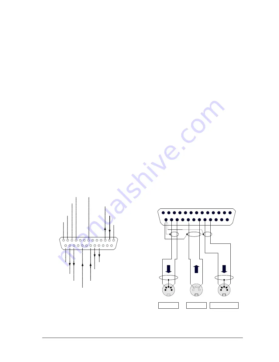
Fig. 4.2/1 shows the actual wiring and pinning
of the 25-pole SUB-D connector.
Please take care to provide individual ground-
connections for every mode, see Fig. 4.2/1
To make the MIDI interface accessible with the
standard 5-pole DIN connectors, an adaptor has
to be made up (or bought in computer shops)
wired up according to Fig. 4.2/2.
Fig. 4.2/1: Pinning of the interface-connector
The MIDI-interface will allow for a simultaneous
controlling of several O 500 C, so one adjustment
in a monitor will be routed to the other systems
as well.
If, for example, two O 500 C are linked together,
the MIDI OUT socket of one monitor is
connected to the MIDI IN socket of the next
monitor, the distance between two boxes may
be up to 15 meters.
In menu
2 Midi Settings
of the System-Menu
the following default adjustments have to be
selected:
Menu:
2 Midi Settings:
Baudrate = MIDI
ParaChg = ON
To select one monitor as the MASTER and the
other one ( ones ) to be the receiving SLAVE,
the slave monitors are selected for „ParaChg“
to OFF. Alternatively the adaptor shown in Fig.
4.2/3 may be used for the interconnection of the
two systems.
Fig. 4.2/2: Wiring scheme of a MIDI adaptor
4.2.1 Wiring of the interface socket
4.2 Control via RS-232 or MIDI
1
13
14
25
(2) RS-232 RX
(1) Chassis GND
(3) RS-232 TX
(7) RS-232 GND
(10) GND
(11) +5 V Out
(12) EE-Clk
(13) EE-Data
(25) MIDI GND
(24) MIDI Out -
(21) MIDI In -
(18) MIDI Through -
25-Pin SUB-D
Connector female
() = Pin No.
(23) MIDI Out +
(19) MIDI In +
(17) MIDI T
(4)
(5)
1
13
14
25
MIDI In
MIDI Through
MIDI Out
+
+
+
(5)
(5)
(4)
(4)
(2)
(2)
25 Pin SUB-D MALE


