background image

22

English

Basic adjustment of auto memory

This receiver memorizes sound settings for each source:
• when you turn off the power, and
• when you change the source.

When you change the source, the memorized settings for the
newly selected source are automatically recalled.
The following can be stored for each source:
• Audio input setting (see page 20)
• Midnight mode (see page 31)
• Volume level for each source when One Touch Operation is

set to “ONE TOUCH OP: ON” (see page 32)

• Speaker output level (see page 36)
• Digital equalization pattern (see page 37)
• Bass boost (see page 37)
• Input attenuator mode (see page 37)
• Surround/DSP mode selection (see page 45)

NOTE

If the source is “FM” or “AM,” you can assign a different setting
for each band.

Signal and speaker indicators on the display

Signal indicators

Speaker indicators

The signal indicators light up as follows:

L:

When digital input is selected:

 Lights up when the

left channel signal comes in.

When analog input is selected:

 Always lights up.

R:

When digital input is selected:

 Lights up when the

right channel signal comes in.

When analog input is selected:

 Always lights up.

C:

Lights up when the center channel signal comes in.

LS:

Lights up when the left surround channel signal comes
in.

RS:

Lights up when the right surround channel signal comes
in.

S:

Lights up when monaural surround signal comes in.

SB:

Lights up when the surround back channel signal
comes in.

LFE: Lights up when the LFE channel signal comes in.

NOTES

• When “A MULTI” is selected in the audio input setting (see

page 20), all the signal indicators except “SB,” “S,” and “LFE”
light up.

• When playing back multi-channel digital sound recorded in

DVD-Audio with HDMI connection (see pages 11 and 20),
the signal indicators may not light up correctly.

The speaker indicators light up as follows:

• The subwoofer indicator (

S.WFR

) lights up when

“SUBWOOFER” is set to “SUBWOOFER: YES.” For details,
see page 28.

• The other speaker indicators light up only when the

corresponding speaker is set to “SMALL” or “LARGE,” and
also when required for the current playback.

LINEAR PCM

L

LS

SB

RS

S.WFR

PL

NEO : 6 DSP
3D-PHONIC

LFE

C

96 / 24

AUTO SURR

VIRTUAL SB

HEADPHONE

x

DIGITAL

DIGITAL AUTO

ANALOG

DUAL MONO

SB

S

SB

R

L

LS

SB

RS

S.WFR

LFE

C

SB

S

SB

R

L

LS

SB

RS

S.WFR

LFE

C

SB

S

SB

R

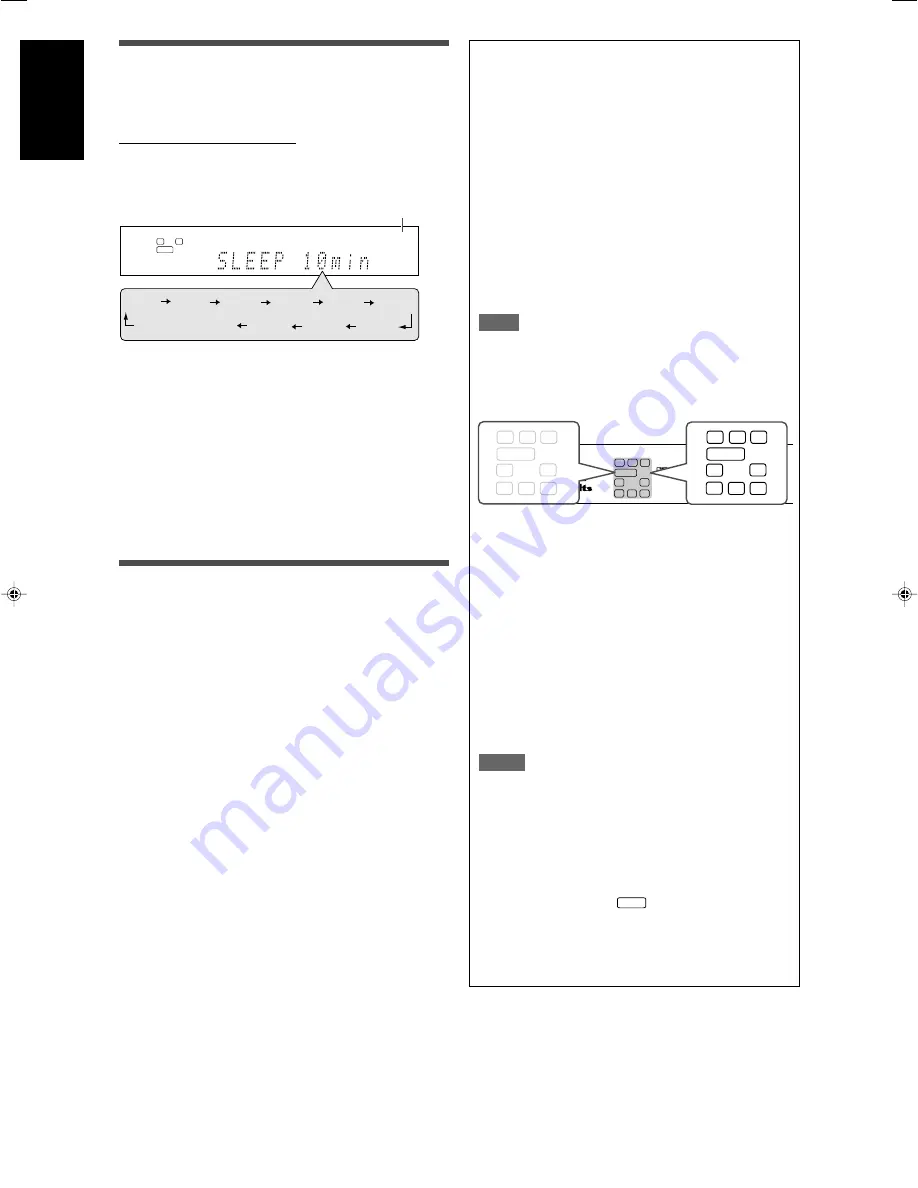
Turning off the power with the Sleep
Timer

You can fall asleep while listening to music—Sleep Timer.

From the remote control ONLY:

Press SLEEP repeatedly.

• Each time you press the button, the shut-off time changes in 10

minute intervals. The SLEEP indicator lights up on the display.

SLEEP indicator

When the shut-off time comes:

The receiver turns off automatically.

To check or change the remaining time until the shut-off
time:

Press SLEEP once.
The remaining time (in minutes) until the shut-off time appears.
• To change the shut-off time, press SLEEP repeatedly.

To cancel the Sleep Timer:

Press SLEEP repeatedly so that “SLEEP OFF” appears on the
display. (The SLEEP indicator goes off.)
• The Sleep Timer is also canceled when you turn off the

receiver.

Making sounds natural

JVC’s CC (Compression Compensative) Converter eliminates
jitter and ripples, achieving a drastic reduction in digital distortion
by processing the digital music data in 24 bit-quantization and by
expanding the sampling frequency to 176.4 kHz (for fs 44.1 kHz
signals)/192 kHz (for fs 48 kHz signals) on the front speakers.
By using the CC Converter, you can obtain a natural sound field
from both digital and analog sources.

Press CC CONVERTER repeatedly.

• Each time you press the button, the mode changes as follows:

CC CNVRTR 1:

Select when playing back an analog
source or a digital source with non
compressed digital sound signal (Linear
PCM).
The CC CONVERTER 1 indicator lights
up on the display.

CC CNVRTR 2:

Select when playing back a source with
compressed digital sound signal (Dolby
Digital or DTS).
The CC CONVERTER 2 indicator lights
up on the display.

CC CNVRTR OFF:

Select when not using the CC Converter.

L

S.WFR

R

AUTO SURR

SLEEP

ANALOG

10min 20min 30min 40min 50min 60min

90min

OFF (canceled)

80min

70min

19-22RX-D702B[C]_f.p65

05.9.14, 1:42 PM

22

Summary of Contents for RX-D701S

Page 1: ...LVT1437 012A A RX D701S AUDIO VIDEO CONTROL RECEIVER INSTRUCTIONS ...

Page 2: ...pparatus When discarding batteries environmental problems must be considered and local rules or laws governing the disposal of these batteries must be followed strictly Do not expose this apparatus to rain moisture dripping or splashing and that no objects filled with liquids such as vases shall be placed on the apparatus Caution Proper Ventilation To avoid risk of electric shock and fire and to p...

Page 3: ...rformance DSP Digital Signal Processor and high capacity memory you can enjoy 7 1 channel surround by playing 2 channel or multi channel software K2 Technology K2 technology has been designed to enable natural audio reproduction achieving a drastic reduction in digital distortion and creating original sound ambience with high precision CC Compression Compensative Converter CC Converter eliminates ...

Page 4: ...Setting the digital input DIGITAL IN terminals DIGITAL IN 1 2 3 31 Setting the Audio delay level AUDIO DELAY 31 Memorizing the volume level for each source ONE TOUCH OP 32 Selecting the source for HDMI terminal and COMPONENT VIDEO jacks HDMI SELECT CMPNT SELECT 32 Selecting the output video signals VIDEO OUTPUT 32 Superimposing the menus SUPERIMPOSE 32 Sound adjustments 33 Basic adjustment items 3...

Page 5: ...ton 20 w DECODE MODE button 21 e SURROUND button 45 r Adjusting buttons for Digital Equalizer 37 D EQ FREQ D EQ LEVEL t CC CONVERTER button 22 y Adjusting buttons for Surround DSP modes parameters C center TONE EFFECT 37 38 u Adjusting buttons for speaker and subwoofer output levels 36 FRONT L FRONT R CENTER SUBWFR SURR L SURR R S BACK L S BACK R i VOLUME button 20 o DVR DVD mode selector 49 52 MU...

Page 6: ...ontrol 20 q PHONES jack 20 w USB terminal 17 e AUX input jacks 15 Digital optical terminal S video jack VIDEO jack AUDIO jacks r Display window 5 t Remote sensor 6 See pages in parentheses for details AUDIO VIDEO CONTROL RECEIVER STANDBY ON CC CONVERTER SETTING ADJUST SURROUND DVR DVD VCR DBS TV USB FM AM SOURCE SELECTOR MULTI JOG MASTER VOLUME SET TUNER PRESET AUX HDMI PUSH OPEN 4 5 6 q 7 8 9 p 3...

Page 7: ...rmat indicators 20 21 41 42 LINEAR PCM 96 24 Signal and speaker indicators 22 NEO 6 indicator 42 VIRTUAL SB surround back indicator 44 3D PHONIC indicator 42 43 DSP indicator 43 and indicator 41 43 Main display B bass BOOST indicator 37 MIDNIGHT indicator 31 _ Frequency unit indicators MHz for FM stations kHz for AM stations 1 ANALOG indicator 20 2 DIGITAL and DIGITAL AUTO indicator 20 21 3 DUAL M...

Page 8: ...dust The temperature around the receiver must be between 5 C and 35 C Make sure there is good ventilation around the receiver Poor ventilation could cause overheating and damage the receiver Leave sufficient distance between the receiver and the TV Handling the receiver Do not insert any metal object into the receiver Do not disassemble the receiver or remove screws covers or cabinet Do not expose...

Page 9: ...n If the reception is poor connect an outdoor single vinyl covered wire not supplied to the AM EXT terminal Keep the AM loop antenna connected FM antenna connection Connect the FM antenna supplied to the FM 75 Ω COAXIAL terminal as a temporary measure Extend the supplied FM antenna horizontally If the reception is poor connect an outdoor FM antenna not supplied Before attaching a 75 Ω coaxial cabl...

Page 10: ...peaker When using one surround back speaker set S BACK OUT to S BACK OUT 1SPK see page 29 and connect the surround back speaker to the left surround back speaker terminal No sound comes from the speaker if you connect it to the right surround back speaker terminal Connecting the powered subwoofer By connecting a subwoofer you can enhance the bass or reproduce the original LFE signals recorded in d...

Page 11: ...k MONITOR OUT or COMPONENT VIDEO jacks MONITOR OUT and a playing video component is connected to the receiver through the HDMI terminal VCR DBS IN or DVR DVD IN you cannot view the playback picture on the TV NOTES When playing back audio and video with the HDMI connection the HDMI lamp on the front panel lights up Set the audio input setting to HDMI when you enjoy sound with the HDMI connection Se...

Page 12: ...uals Do not connect the AC power plug to the wall outlet until all connections are completed signal current DO NOT use a TV through a VCR or a TV with a built in VCR otherwise the picture may be distorted S video cable not supplied Stereo audio cable not supplied Composite video cable not supplied Red White NOTES If connecting a TV only with the HDMI cable and setting the video input setting see p...

Page 13: ...und as well using a digital audio cable coaxial or optical When shipped from the factory the digital coaxial terminal DIGITAL IN 1 DVR DVD on the rear of the receiver is set for a DVD recorder and DVD player For details of digital audio connection see page 16 If your DVD recorder or DVD player is equipped with the analog multi channel output terminals you can enjoy the sound recorded in DVD Audio ...

Page 14: ... connections When you connect other components refer also to their manuals When you enjoy sound recorded in DVD Audio You can enjoy sound recorded in DVD Audio both with analog or digital methods With analog method connect your DVD recorder or DVD player to this receiver according to the diagram above select A MULTI in the audio input setting See page 20 With digital method connect your DVD record...

Page 15: ...digital sound as well using a digital audio cable coaxial or optical When shipped from the factory the digital optical terminal DIGITAL IN 3 VCR on the rear of the receiver is set for a VCR For details of digital audio connection see page 16 When connecting a VCR with a HDMI cable or component video cable set HDMI SELECT or CMPNT SELECT to VCR see page 32 signal current Available video input setti...

Page 16: ...tion to using the HDMI cable you can enjoy digital sound as well using a digital audio cable coaxial or optical When shipped from the factory the digital optical terminal DIGITAL IN 2 DBS on the rear of the receiver is set for a DBS tuner For details of digital audio connection see page 16 When connecting a DBS tuner with a HDMI cable or component video cable set HDMI SELECT or CMPNT SELECT to DBS...

Page 17: ...e page 20 for details Stereo audio cable not supplied Composite video cable not supplied S video cable not supplied Digital optical cable not supplied Video camera etc signal current Available video input setting for each video output setting Available Not available HDMI CMPNT S C HDMI CMPNT S C VIDEO INPUT VIDEO OUTPUT Select the appropriate VIDEO INPUT see page 20 according to the connection you...

Page 18: ...ecting a digital optical cable unplug the protective plug NOTES The digital signal format transmitted through the DIGITAL OUT terminal is the same as that of the input signal For example when the DTS signals are coming the DTS signals are transmitted The digital audio signals coming through the following terminals cannot be transmitted through the DIGITAL OUT terminal USB WIRELESS ANTENNA terminal...

Page 19: ...smitter light up 4 Turn on the receiver then slide the USB WIRELESS switch on the rear to ID LEARNING and select the source as USB WIRELESS When you slide the switch the lamp in the switch starts flashing 5 Set the volume to minimum IMPORTANT Always set volume to 0 when connecting or disconnecting the other equipment 6 Press and hold ID on the transmitter to make a wireless communication with the ...

Page 20: ... window appears and you can check whether the drivers are installed If no sound comes from the speakers check the following items For both USB WIRELESS and USB TERMINAL check the USB device is recognized properly check the playback software in your PC is compatible with the USB device open the Control Panel on your PC select Sounds and Audio Devices Audio tab Sound playback Default device and chec...

Page 21: ...MINAL press USB Each time you press USB the mode alternates between USB WIRELESS and USB TERMINAL Source lamps 1 Turn on the power Press STANDBY ON or AUDIO on the remote control The standby lamp goes off and the source lamp of the current source lights in red Current source name appears To turn off the power into standby Press STANDBY ON or AUDIO on the remote control again The standby lamp light...

Page 22: ...1 to 15 From the remote control ONLY Press VIDEO INPUT to select the video input setting Each time you press the button the input setting changes as follows This setting is memorized for each source NOTES For VCR and DBS you can select HDMI and CMPNT for the source you assigned in HDMI SELECT and CMPNT SELECT see page 32 When the video input setting and the audio input setting are both set to HDMI...

Page 23: ...CH PCM appears on the display for a while Lights up when Dolby Digital signal comes in Flashes when DOLBY DIGITAL is selected for any software other than Dolby Digital Lights up when conventional DTS signal comes in Flashes when DTS is selected for any software other than DTS 96 24 Lights up when DTS 96 24 signal comes in NOTE When DGTL AUTO cannot recognize the incoming signal no digital signal f...

Page 24: ...light up only when the corresponding speaker is set to SMALL or LARGE and also when required for the current playback LINEAR PCM L LS SB RS S WFR PL NEO 6 DSP 3D PHONIC LFE C 96 24 AUTO SURR VIRTUAL SB HEADPHONE x DIGITAL DIGITALAUTO ANALOG DUAL MONO SB S SB R L LS SB RS S WFR LFE C SB S SB R L LS SB RS S WFR LFE C SB S SB R Turning off the power with the Sleep Timer You can fall asleep while list...

Page 25: ...d Setup the speaker distance and output level you have set before will be inactive You can see the setting process on the TV screen and the display during Smart Surround Setup If you have turned off the display cancel the Dimmer see page 21 otherwise you cannot see the information on the display Smart Surround Setup will not be done correctly if you or other object blocks the sound When you change...

Page 26: ...er fails to detect the sound three times The receiver exits from Smart Surround Setup To cancel Smart Surround Setup press EXIT while SETTING UP flashes No other operations can be accepted after SETTING UP stops flashing Complete the Smart Surround Setup To check the current setting made by Smart Surround Setup press SMART S SETUP while the receiver is in normal operation mode The setting values a...

Page 27: ...lect the Dual Mono sound channel 30 DUAL MONO SUBWFR OUT Select sounds emitted from the subwoofer 30 SUBWOOFER OUT CROSSOVER Select the cutoff frequency to the subwoofer 31 CROSSOVER LFE ATT Attenuate the bass LFE sounds 31 LFE ATT MIDNIGHT Reproduce a powerful sound at night 31 MIDNIGHT MODE DIGITAL IN 1 Select the component connected to the digital DIGITAL IN 1 coaxial terminal 1 DVR DVD 31 DIGI...

Page 28: ... OUT LFE CROSSOVER 100Hz LFE ATT 0dB MIDNIGHT OFF ENTER EXIT DUAL MONO SUBWOOFER OUT LFE ATT MIDNIGHT MODE DIGITAL IN 1 DIGITAL IN 2 DIGITAL IN 3 ONE TOUCH OPERATION HDMI SELECT COMPONENT SELECT VIDEO OUTPUT AUDIO DELAY SUPERIMPOSE See page 28 See page 28 See page 28 See page 28 See page 28 See page 29 See page 29 See page 29 See page 29 See page 29 See page 29 See page 29 See page 29 See page 29 ...

Page 29: ... 1 to SETTING MENU 5 To change the screen simply pressing 5 or repeatedly You can go to the next previous screen On the front panel turn MULTI JOG The submenu previously selected appears Operations On the TV screen On the display Usable buttons and their functions Usable buttons and their functions Button indications on the screen The buttons for operating the menu are shown on the TV screen You c...

Page 30: ...from the Surround and DSP modes register the setting about the speaker after all connections are completed 7 Setting subwoofer information SUBWOOFER Select whether you have connected a subwoofer or not SUBWOOFER YES Select when you have connected a subwoofer The subwoofer indicator S WFR lights up on the display You can adjust the subwoofer output level see page 36 SUBWOOFER NO Select when you hav...

Page 31: ... S BACK SPK is set to NO you cannot select S BACK OUT When S BACK OUT is set to S BACK OUT 1SPK connect the surround back speaker to the left surround back speaker terminal see page 8 No sound comes from the surround back speaker if you connect it to the right surround back speaker terminal 7 Setting the speaker distance The distance from your listening point to the speakers is one of the importan...

Page 32: ...ing software with the LFE signals Dolby Digital multi channel software DTS multi channel software When playing analog source or linear PCM software no LFE signals are emitted Activating the EX ES PLIIx setting EX ES PLIIx Depending on this setting available Surround modes for digital multi channel software vary EX ES PLIIx reproduction or 5 1 channel reproduction Select an appropriate setting for ...

Page 33: ...r in any position this receiver automatically reallocates the bass sound elements assigned to the small speaker to the large speakers To use this function properly set this crossover frequency level according to the size of the small speaker connected If you have selected LARGE for all speakers see page 28 this function will not take effect CROSS OFF appears CROSSOVER 80Hz Select when the cone spe...

Page 34: ...H OP This receiver memorizes some settings separately for each source In addition you can store the volume level for each source with the other memorized settings See page 22 This receiver memorizes the volume level when you turn off the power and when you change the source ONE TOUCH OP ON Select to store the volume level separately for each source The ONE TOUCH OPERATION indicator lights up on th...

Page 35: ...ect level 37 EFFECT ROOM SIZE Select the room size for your virtual listening ROOM SIZE room 37 LIVENESS Select the liveness level for your virtual LIVENESS listening room 38 PANORAMA Add wraparound sound effect with side PANORAMA wall image 38 CENTER WIDTH Adjust the center channel localization CENTER WIDTH between the center speaker and the left right speakers 38 Items To do DIMENSION Adjust sou...

Page 36: ...T OFF ENTER EXIT CENTER WIDTH PANORAMA CENTER GAIN CENTER TONE DIMENSION CNTR ALIGNMENT See page 37 See page 37 See page 37 See page 37 See page 37 See page 37 See page 37 See page 37 See page 37 See page 38 See page 38 See page 38 See page 38 See page 38 See page 38 See page 38 See page 36 See page 36 See page 36 See page 36 See page 36 See page 36 See page 36 See page 36 Press SET Setup menu con...

Page 37: ...iate setting press 2 or 3 repeatedly then press SET The on screen display returns to the previous ADJUST MENU In this example ADJUST MENU 1 appears on the TV screen and SUBWFR LVL appears on the display On the front panel turn MULTI JOG then press SET 5 Repeat steps 2 to 4 to set other items if necessary The submenu previously selected appears On the TV screen On the display The setting item previ...

Page 38: ...sting the speaker output levels SUBWOOFER LEVEL subwoofer output level FRONT L LEVEL left front speaker output level FRONT R LEVEL right front speaker output level CENTER LEVEL center speaker output level SURR L LEVEL left surround speaker output level SURR R LEVEL right surround speaker output level S BACK L LEVEL left surround back speaker output level S BACK R LEVEL right surround back speaker ...

Page 39: ...ot adjust this item directly from the remote control Adjustable range 1 to 5 in 1 step intervals Initial setting ROOM SIZE 3 As the number increases the interval between reflections increases so that you will feel as if you were in a larger room Normally select 3 Adjusting the equalization patterns DIGITAL EQ 63Hz 250Hz 1kHz 4kHz 16kHz You can adjust equalization patterns in five frequency bands c...

Page 40: ...Once you have made an adjustment it is memorized for each DSP mode You cannot adjust this item directly from the remote control Adjustable range 1 to 5 in 1 step intervals Initial setting LIVENESS 3 As the number increases the attenuation level of reflections over time decreases so that acoustics change from Dead to Live Normally select 3 7 Adjusting the panorama control for Pro Logic IIx Music an...

Page 41: ...et stations Before you start remember There is a time limit in doing the following steps If the setting is canceled before you finish start from step 2 again From the remote control ONLY 1 Tune in to the station you want to preset see Tuning in to stations manually above If you want to store the FM reception mode for this station select the FM reception mode you want See Selecting the FM reception...

Page 42: ...d station of the selected band is tuned in 2 Press TUNER PRESET P appears on the display and MULTI JOG now works for selecting preset channels 3 Turn MULTI JOG to select a preset channel number To increase the preset channel numbers turn MULTI JOG clockwise To decrease the preset channel numbers turn MULTI JOG counterclockwise Selecting the FM reception mode When an FM stereo broadcast is hard to ...

Page 43: ...olby Digital EX Dolby Digital EX DOLBY D EX is a digital surround encoding format that adds the third surround channels called surround back Compared to the conventional Dolby Digital 5 1CH these newly added surround back channels can reproduce more detailed movements behind you while viewing the video software In addition surround sound localization will become more stable Dolby Surround Dolby Pr...

Page 44: ... 1 channel or 6 1 channel that developed from Dolby Pro Logic II The matrix based conversion method used for Dolby Pro Logic IIx makes no limitation for the cutoff frequency of the surround treble This receiver provides three types of Dolby Pro Logic IIx modes Pro Logic IIx Movie PLIIx MOVIE Pro Logic IIx Music PLIIx MUSIC and Pro Logic IIx Game PLIIx GAME When Dolby Pro Logic IIx is activated PLI...

Page 45: ...ed while playing back 2 channel analog or digital source the built in Dolby Pro Logic II decoder is activated and the indicator lights up Early reflections Direct sounds Reflections from behind When using the DAP mode the sounds come out of all the connected and activated speakers If SURROUND SPK is set to NO in the speaker setting see page 28 JVC s original 3D PHONIC processing which has been dev...

Page 46: ...ctivated If you want to apply the processing set the EX ES PLIIx setting to OFF see page 30 2 When S BACK OUT is set to SB OUT 1SPK D PLIIx MOVIE is changed to DOLBY D EX and DTS PLIIx MOVIE is changed to DTS EX 3 When S BACK SPK is set to NO Virtual Surround Back is activated for the modes and the VIRTUAL SB indicator lights up on the display 4 When S BACK SPK is set to NO PLllx MOVIE PLllx MUSIC...

Page 47: ... settings and the incoming signals For details see page 44 Activating one of the Surround DSP modes automatically recalls the memorized settings and adjustments To adjust the speaker output level see page 36 When activating one of the Surround DSP modes you can adjust CENTER TONE see page 38 When activating one of the Surround DSP modes except PLIIx MUSIC PLII MUSIC NEO 6 MUSIC and ALL CH STEREO y...

Page 48: ...eiver through one type of video terminals can output only through the terminal of the same type So you need to connect the video components to this receiver using one of the following three ways When using the AV COMPU LINK remote control system set the video output and video input setting for the DVD player and the VCR correctly see Selecting the video input setting on page 20 and Selecting the o...

Page 49: ...e recording Connecting procedure 1 If you have already plugged your VCR DVD player TV and this receiver into the AC outlets unplug their AC power cords first 2 Connect your VCR DVD player TV and this receiver as follows using the cables with the monaural mini plugs not supplied See Connections 1 on the previous page 3 Connect the audio input output jacks on the VCR DVD player TV and this receiver ...

Page 50: ...C products 7 VCR You can always perform the following operation VCR Turn on or off the VCR After pressing VCR you can perform the following operations on the VCR CHANNEL Change the channel numbers on the VCR 1 9 0 Select the channel numbers on the VCR 3 Start playback 7 Stop playback 8 Pause playback To release it press 3 FF Fast wind a tape REW Rewind a tape 3 Start recording 8 Enter recording pa...

Page 51: ...le number track number menu item etc If these buttons do not function normally use the remote control supplied with your DVD recorder or DVD player Refer also to the manuals supplied with the DVD recorder or DVD player for details 1 2 3 4 5 6 7 8 9 10 0 10 After setting the mode selector correctly you can perform the following operations on the DVD recorder or DVD player See the instructions suppl...

Page 52: ...either TV or VIDEO After pressing TV you can perform the following operations on the TV CHANNEL Change the channel numbers 1 9 0 100 10 Select the channel numbers See the instructions supplied with the TV for details 5 Try to operate your TV by pressing TV When your TV turns on or off you have entered the correct code If more than one code is listed for your brand of TV try each one until the corr...

Page 53: ...ctions supplied with the VCR for details 5 Try to operate your VCR by pressing VCR When your VCR turns on or off you have entered the correct code If more than one code is listed for your brand of VCR try each one until the correct one is entered Manufacturers codes for VCR Manufacturers codes are subject to change without notice If they are changed this remote control cannot operate the equipment...

Page 54: ...one until the correct one is entered Manufacturer Codes JVC 01 Hitachi 02 Kenwood 03 04 Magnavox 05 Marantz 06 Mitsubishi 07 Onkyo 08 09 Panasonic 10 Philips 06 Pioneer 11 Proscan 12 RCA 12 Samsung 13 Sony 14 Toshiba 05 Yamaha 15 Zenith 05 16 Initial setting 01 Manufacturers codes are subject to change without notice If they are changed this remote control cannot operate the equipment Changing the...

Page 55: ...ELECT see page 32 is not assigned for each source correctly The video input setting is set to HDMI A video or audio format not compatible with this receiver is played A HDCP compatible TV is not connected The receiver failed to recognize HDMI connected components A HDMI cable longer than 5 m 15 ft is used SOLUTION Plug the power cord into an AC outlet 1 Stop the playback source 2 Turn on the recei...

Page 56: ...ion Incoming signal is too weak The station is too far away The wrong antenna is being used Antennas are not connected properly Ignition noise from automobiles SOLUTION Set the mode selector correctly then press the corresponding source selecting button before operation Remove the obstruction Replace batteries Set the mode selector to the proper position Connect an outdoor FM antenna or contact yo...

Page 57: ...esponse 6 Ω 20 Hz to 20 kHz 1 dB Bass Boost 4 dB 1 dB at 100 Hz Equalization at DSP operation Center frequency 63 Hz 250 Hz 1 kHz 4 kHz 16 kHz Control range 8 dB Specifications Video Video Input Sensitivity Impedance Composite video DVR DVD VCR DBS 1 V p p 75 Ω S video DVR DVD VCR DBS Y luminance 1 V p p 75 Ω C chrominance burst 0 3 V p p 75 Ω Component DVR DVD VCR DBS Y luminance 1 V p p 75 Ω PB ...

Page 58: ...1105RYMMDWJEIN EN 2005 Victor Company of Japan Limited AUDIO VIDEO CONTROL RECEIVER RX D701S ...

Page 59: ...UDIO VIDEO CONTROL RECEIVER INSTRUCTIONS For Customer Use Enter below the Model No and Serial No which are located either on the rear bottom or side of the cabinet Retain this information for future reference Model No Serial No ...

Page 60: ...ns 1 This device may not cause harmful interference 2 This device must accept any interference received including interference that may cause undesired operation Responsible Party JVC Americas Corp Address 1700 Valley Road Wayne New Jersey 07470 Telephone Number 973 317 5000 For Canada pour le Canada This Class B digital apparatus complies with Canadian ICES 003 Cet appareil numérique de la classe...

Page 61: ...y memory you can enjoy 7 1 channel surround by playing 2 channel or multi channel software K2 Technology K2 technology has been designed to enable natural audio reproduction achieving a drastic reduction in digital distortion and creating original sound ambience with high precision CC Compression Compensative Converter CC Converter eliminates jitter and ripples achieving a drastic reduction in dig...

Page 62: ...T 31 Setting the digital input DIGITAL IN terminals DIGITAL IN 1 2 3 31 Setting the Audio delay level AUDIO DELAY 31 Memorizing the volume level for each source ONE TOUCH OP 32 Selecting the source for HDMI terminal and COMPONENT VIDEO jacks HDMI SELECT CMPNT SELECT 32 Selecting the output video signals VIDEO OUTPUT 32 Superimposing the menus SUPERIMPOSE 32 Sound adjustments 33 Basic adjustment it...

Page 63: ... INPUT button 20 q AUDIO INPUT button 20 w DECODE MODE button 21 e SURROUND button 30 45 r Adjusting buttons for Digital Equalizer 37 D EQ FREQ D EQ LEVEL t CC CONVERTER button 22 y Adjusting buttons for Surround DSP modes parameters C center TONE EFFECT 37 38 u Adjusting buttons for speaker and subwoofer output levels 36 FRONT L FRONT R CENTER SUBWFR SURR L SURR R S BACK L S BACK R i VOLUME butto...

Page 64: ...PEN Front panel 1 STANDBY ON button and standby lamp 19 2 CC CONVERTER button 22 3 SETTING button 25 27 4 ADJUST button 33 35 5 SURROUND button 45 6 HDMI lamp 9 20 7 Source lamps 19 DVR DVD VCR DBS TV SIRIUS USB FM AM AUX 8 SET button 25 28 33 35 TUNER PRESET button 40 9 SOURCE SELECTOR 19 40 MULTI JOG 25 27 28 33 35 45 p MASTER VOLUME control 20 q PHONES jack 20 w USB terminal 17 e AUX input jack...

Page 65: ... ANALOG indicator 20 2 DIGITAL and DIGITAL AUTO indicator 20 21 3 DUAL MONO indicator 30 4 AUTO SURR surround indicator 45 5 HEADPHONE indicator 20 43 6 CC CONVERTER 1 and CC CONVERTER 2 indicator 22 7 Tuner operation indicators 39 TUNED STEREO 8 DIGITAL EQ indicator 37 9 AUTO MUTING indicator 40 0 C center TONE indicator 38 ONE TOUCH OPERATION indicator 32 INPUT ATT attenuate indicator 37 SLEEP i...

Page 66: ...e temperature around the receiver must be between 5 C and 35 C 23 F and 95 F Make sure there is good ventilation around the receiver Poor ventilation could cause overheating and damage the receiver Leave sufficient distance between the receiver and the TV Handling the receiver Do not insert any metal object into the receiver Do not disassemble the receiver or remove screws covers or cabinet Do not...

Page 67: ...n If the reception is poor connect an outdoor single vinyl covered wire not supplied to the AM EXT terminal Keep the AM loop antenna connected FM antenna connection Connect the FM antenna supplied to the FM 75 Ω COAXIAL terminal as a temporary measure Extend the supplied FM antenna horizontally If the reception is poor connect an outdoor FM antenna not supplied Before attaching a 75 Ω coaxial cabl...

Page 68: ...peaker When using one surround back speaker set S BACK OUT to S BACK OUT 1SPK see page 29 and connect the surround back speaker to the left surround back speaker terminal No sound comes from the speaker if you connect it to the right surround back speaker terminal Connecting the powered subwoofer By connecting a subwoofer you can enhance the bass or reproduce the original LFE signals recorded in d...

Page 69: ...O jack MONITOR OUT or COMPONENT VIDEO jacks MONITOR OUT and a playing video component is connected to the receiver through the HDMI terminal VCR DBS IN or DVR DVD IN you cannot view the playback picture on the TV NOTES When playing back audio and video with the HDMI connection the HDMI lamp on the front panel lights up Set the audio input setting to HDMI when you enjoy sound with the HDMI connecti...

Page 70: ...MI the on screen display does not appear on the TV screen When using on screen display set the video input setting to the setting other than HDMI Select the audio and video input setting according to the connection method See page 20 for details In addition to using the HDMI cable you can enjoy digital sound as well using a digital audio cable coaxial or optical For details of digital audio connec...

Page 71: ...und as well using a digital audio cable coaxial or optical When shipped from the factory the digital coaxial terminal DIGITAL IN 1 DVR DVD on the rear of the receiver is set for a DVD recorder and DVD player For details of digital audio connection see page 16 If your DVD recorder or DVD player is equipped with the analog multi channel output terminals you can enjoy the sound recorded in DVD Audio ...

Page 72: ...e HDMI cables See page 11 select HDMI in the audio input setting See page 20 NOTES When selecting A MULTI in the audio input setting or when multi channel PCM signals see page 42 are coming in with selecting HDMI in the audio input setting you can listen to the front channel sounds left and right only by using the headphones 3D HEADPHONE mode see page 43 is not available When selecting A MULTI in ...

Page 73: ...can enjoy digital sound as well using a digital audio cable coaxial or optical When shipped from the factory the digital optical terminal DIGITAL IN 3 VCR on the rear of the receiver is set for a VCR For details of digital audio connection see page 16 When connecting a VCR with a HDMI cable or component video cable set HDMI SELECT or CMPNT SELECT to VCR see page 32 signal current Available video i...

Page 74: ...pped from the factory the digital optical terminal DIGITAL IN 2 DBS on the rear of the receiver is set for a DBS tuner For details of digital audio connection see page 16 When connecting a DBS tuner with a HDMI cable or component video cable set HDMI SELECT or CMPNT SELECT to DBS see page 32 DBS tuner signal current Available video input setting for each video output setting Available Not availabl...

Page 75: ...ble Not available HDMI CMPNT S C HDMI CMPNT S C VIDEO INPUT VIDEO OUTPUT Select the appropriate VIDEO INPUT see page 20 according to the connection you have made If you do not you cannot view the playback picture on the TV How to open the front door Red White Turn off all components before making connections When you connect other components refer also to their manuals 7 Connecting a SIRIUS radio ...

Page 76: ...ecting a digital optical cable unplug the protective plug NOTES The digital signal format transmitted through the DIGITAL OUT terminal is the same as that of the input signal For example when the DTS signals are coming the DTS signals are transmitted The digital audio signals coming through the following terminals cannot be transmitted through the DIGITAL OUT terminal USB WIRELESS ANTENNA terminal...

Page 77: ...ter light up ANTENNA USB WIRELESS LEARNING ID ON USB 4 Turn on the receiver then slide the USB WIRELESS switch on the rear to ID LEARNING and select the source as USB WIRELESS When you slide the switch the lamp in the switch starts flashing 5 Set the volume to minimum IMPORTANT Always set volume to 0 when connecting or disconnecting the other equipment 6 Press and hold ID on the transmitter to mak...

Page 78: ... window appears and you can check whether the drivers are installed If no sound comes from the speakers check the following items For both USB WIRELESS and USB TERMINAL check the USB device is recognized properly check the playback software in your PC is compatible with the USB device open the Control Panel on your PC select Sounds and Audio Devices Audio tab Sound playback Default device and chec...

Page 79: ...front panel ONLY Press SET when TV is selected as the source ASSIGN SIRIUS appears on the display for a while When you change the source name to TV press SET when SIRIUS is selected as the source ASSIGN TV appears on the display for a while NOTE When you change the source name to SIRIUS you cannot select TV as the source Source lamps 1 Turn on the power Press STANDBY ON or AUDIO on the remote cont...

Page 80: ...on pages 11 to 15 From the remote control ONLY Press VIDEO INPUT to select the video input setting Each time you press the button the input setting changes as follows This setting is memorized for each source NOTES For VCR and DBS you can select HDMI and CMPNT for the source you assigned in HDMI SELECT and CMPNT SELECT see page 32 When the video input setting and the audio input setting are both s...

Page 81: ...CH PCM appears on the display for a while Lights up when Dolby Digital signal comes in Flashes when DOLBY DIGITAL is selected for any software other than Dolby Digital Lights up when conventional DTS signal comes in Flashes when DTS is selected for any software other than DTS 96 24 Lights up when DTS 96 24 signal comes in NOTE When DGTL AUTO cannot recognize the incoming signal no digital signal f...

Page 82: ...light up only when the corresponding speaker is set to SMALL or LARGE and also when required for the current playback LINEAR PCM L LS SB RS S WFR PL NEO 6 DSP 3D PHONIC LFE C 96 24 AUTO SURR VIRTUAL SB HEADPHONE x DIGITAL DIGITALAUTO ANALOG DUAL MONO SB S SB R L LS SB RS S WFR LFE C SB S SB R L LS SB RS S WFR LFE C SB S SB R Turning off the power with the Sleep Timer You can fall asleep while list...

Page 83: ...display during Smart Surround Setup If you have turned off the display cancel the Dimmer see page 21 otherwise you cannot see the information on the display Smart Surround Setup will not be done correctly if you or other object blocks the sound When you change your speakers do the following procedure again In this section the on screen display on the TV screen is used for explaining The on screen ...

Page 84: ...er fails to detect the sound three times The receiver exits from Smart Surround Setup To cancel Smart Surround Setup press EXIT while SETTING UP flashes No other operations can be accepted after SETTING UP stops flashing Complete the Smart Surround Setup To check the current setting made by Smart Surround Setup press SMART S SETUP while the receiver is in normal operation mode The setting values a...

Page 85: ...lect the Dual Mono sound channel 30 DUAL MONO SUBWFR OUT Select sounds emitted from the subwoofer 30 SUBWOOFER OUT CROSSOVER Select the cutoff frequency to the subwoofer 31 CROSSOVER LFE ATT Attenuate the bass LFE sounds 31 LFE ATT MIDNIGHT Reproduce a powerful sound at night 31 MIDNIGHT MODE DIGITAL IN 1 Select the component connected to the digital DIGITAL IN 1 coaxial terminal 1 DVR DVD 31 DIGI...

Page 86: ... OUT LFE CROSSOVER 100Hz LFE ATT 0dB MIDNIGHT OFF ENTER EXIT DUAL MONO SUBWOOFER OUT LFE ATT MIDNIGHT MODE DIGITAL IN 1 DIGITAL IN 2 DIGITAL IN 3 ONE TOUCH OPERATION HDMI SELECT COMPONENT SELECT VIDEO OUTPUT AUDIO DELAY SUPERIMPOSE See page 28 See page 28 See page 28 See page 28 See page 28 See page 29 See page 29 See page 29 See page 29 See page 29 See page 29 See page 29 See page 29 See page 29 ...

Page 87: ... 1 to SETTING MENU 5 To change the screen simply pressing 5 or repeatedly You can go to the next previous screen On the front panel turn MULTI JOG The submenu previously selected appears Operations On the TV screen On the display Usable buttons and their functions Usable buttons and their functions Button indications on the screen The buttons for operating the menu are shown on the TV screen You c...

Page 88: ...ound and DSP modes register the setting about the speaker after all connections are completed 7 Setting subwoofer information SUBWOOFER Select whether you have connected a subwoofer or not SUBWOOFER YES Select when you have connected a subwoofer The subwoofer indicator S WFR lights up on the display You can adjust the subwoofer output level see page 36 SUBWOOFER NO Select when you have disconnecte...

Page 89: ... S BACK SPK is set to NO you cannot select S BACK OUT When S BACK OUT is set to S BACK OUT 1SPK connect the surround back speaker to the left surround back speaker terminal see page 8 No sound comes from the surround back speaker if you connect it to the right surround back speaker terminal 7 Setting the speaker distance The distance from your listening point to the speakers is one of the importan...

Page 90: ...ing software with the LFE signals Dolby Digital multi channel software DTS multi channel software When playing analog source or linear PCM software no LFE signals are emitted Activating the EX ES PLIIx setting EX ES PLIIx Depending on this setting available Surround modes for digital multi channel software vary EX ES PLIIx reproduction or 5 1 channel reproduction Select an appropriate setting for ...

Page 91: ...s receiver automatically reallocates the bass sound elements assigned to the small speaker to the large speakers To use this function properly set this crossover frequency level according to the size of the small speaker connected If you have selected LARGE for all speakers see page 28 this function will not take effect CROSS OFF appears CROSSOVER 80Hz Select when the cone speaker unit built in th...

Page 92: ...H OP This receiver memorizes some settings separately for each source In addition you can store the volume level for each source with the other memorized settings See page 22 This receiver memorizes the volume level when you turn off the power and when you change the source ONE TOUCH OP ON Select to store the volume level separately for each source The ONE TOUCH OPERATION indicator lights up on th...

Page 93: ...ect level 37 EFFECT ROOM SIZE Select the room size for your virtual listening ROOM SIZE room 37 LIVENESS Select the liveness level for your virtual LIVENESS listening room 38 PANORAMA Add wraparound sound effect with side PANORAMA wall image 38 CENTER WIDTH Adjust the center channel localization CENTER WIDTH between the center speaker and the left right speakers 38 Items To do DIMENSION Adjust sou...

Page 94: ...MENU 2 5 DIGITAL EQ 63Hz 0 DIGITAL EQ 250Hz 0 DIGITAL EQ 1kHz 0 DIGITAL EQ 4kHz 0 DIGITAL EQ 16kHz 0 BASS BOOST OFF ENTER EXIT SUBWOOFER LEVEL FRONT L LEVEL FRONT R LEVEL CENTER LEVEL SURR L LEVEL DIGITAL EQ 63Hz DIGITAL EQ 4kHz DIGITAL EQ 16kHz DIGITAL EQ 1kHz BASS BOOST SURR R LEVEL LIVENESS ADJUST MENU 3 5 INPUT ATT NORMAL EFFECT 3 ROOM SIZE 3 LIVENESS 3 ENTER EXIT INPUT ATT EFFECT ROOM SIZE S ...

Page 95: ...iate setting press 2 or 3 repeatedly then press SET The on screen display returns to the previous ADJUST MENU In this example ADJUST MENU 1 appears on the TV screen and SUBWFR LVL appears on the display On the front panel turn MULTI JOG then press SET 5 Repeat steps 2 to 4 to set other items if necessary The submenu previously selected appears On the TV screen On the display The setting item previ...

Page 96: ...usting the speaker output levels SUBWOOFER LEVEL subwoofer output level FRONT L LEVEL left front speaker output level FRONT R LEVEL right front speaker output level CENTER LEVEL center speaker output level SURR L LEVEL left surround speaker output level SURR R LEVEL right surround speaker output level S BACK L LEVEL left surround back speaker output level S BACK R LEVEL right surround back speaker...

Page 97: ...ot adjust this item directly from the remote control Adjustable range 1 to 5 in 1 step intervals Initial setting ROOM SIZE 3 As the number increases the interval between reflections increases so that you will feel as if you were in a larger room Normally select 3 Adjusting the equalization patterns DIGITAL EQ 63Hz 250Hz 1kHz 4kHz 16kHz You can adjust equalization patterns in five frequency bands c...

Page 98: ...Once you have made an adjustment it is memorized for each DSP mode You cannot adjust this item directly from the remote control Adjustable range 1 to 5 in 1 step intervals Initial setting LIVENESS 3 As the number increases the attenuation level of reflections over time decreases so that acoustics change from Dead to Live Normally select 3 7 Adjusting the panorama control for Pro Logic IIx Music an...

Page 99: ...d 15 AM stations To store the preset stations Before you start remember There is a time limit in doing the following steps If the setting is canceled before you finish start from step 2 again From the remote control ONLY 1 Tune in to the station you want to preset see Tuning in to stations manually above If you want to store the FM reception mode for this station select the FM reception mode you w...

Page 100: ... select FM or AM The last received station of the selected band is tuned in 2 Press TUNER PRESET P appears on the display and MULTI JOG now works for selecting preset channels 3 Turn MULTI JOG to select a preset channel number To increase the preset channel numbers turn MULTI JOG clockwise To decrease the preset channel numbers turn MULTI JOG counterclockwise Selecting the FM reception mode When a...

Page 101: ...olby Digital EX Dolby Digital EX DOLBY D EX is a digital surround encoding format that adds the third surround channels called surround back Compared to the conventional Dolby Digital 5 1CH these newly added surround back channels can reproduce more detailed movements behind you while viewing the video software In addition surround sound localization will become more stable Dolby Surround Dolby Pr...

Page 102: ... 1 channel or 6 1 channel that developed from Dolby Pro Logic II The matrix based conversion method used for Dolby Pro Logic IIx makes no limitation for the cutoff frequency of the surround treble This receiver provides three types of Dolby Pro Logic IIx modes Pro Logic IIx Movie PLIIx MOVIE Pro Logic IIx Music PLIIx MUSIC and Pro Logic IIx Game PLIIx GAME When Dolby Pro Logic IIx is activated PLI...

Page 103: ...ed while playing back 2 channel analog or digital source the built in Dolby Pro Logic II decoder is activated and the indicator lights up Early reflections Direct sounds Reflections from behind When using the DAP mode the sounds come out of all the connected and activated speakers If SURROUND SPK is set to NO in the speaker setting see page 28 JVC s original 3D PHONIC processing which has been dev...

Page 104: ...ctivated If you want to apply the processing set the EX ES PLIIx setting to OFF see page 30 2 When S BACK OUT is set to SB OUT 1SPK D PLIIx MOVIE is changed to DOLBY D EX and DTS PLIIx MOVIE is changed to DTS EX 3 When S BACK SPK is set to NO Virtual Surround Back is activated for the modes and the VIRTUAL SB indicator lights up on the display 4 When S BACK SPK is set to NO PLllx MOVIE PLllx MUSIC...

Page 105: ... settings and the incoming signals For details see page 44 Activating one of the Surround DSP modes automatically recalls the memorized settings and adjustments To adjust the speaker output level see page 36 When activating one of the Surround DSP modes you can adjust CENTER TONE see page 38 When activating one of the Surround DSP modes except PLIIx MUSIC PLII MUSIC NEO 6 MUSIC and ALL CH STEREO y...

Page 106: ...eiver through one type of video terminals can output only through the terminal of the same type So you need to connect the video components to this receiver using one of the following three ways When using the AV COMPU LINK remote control system set the video output and video input setting for the DVD player and the VCR correctly see Selecting the video input setting on page 20 and Selecting the o...

Page 107: ...e recording Connecting procedure 1 If you have already plugged your VCR DVD player TV and this receiver into the AC outlets unplug their AC power cords first 2 Connect your VCR DVD player TV and this receiver as follows using the cables with the monaural mini plugs not supplied See Connections 1 on the previous page 3 Connect the audio input output jacks on the VCR DVD player TV and this receiver ...

Page 108: ...channel numbers RETURN 10 Switch between the previous channel and the current channel 7 VCR 7 SIRIUS radio You can always perform the following operation VCR Turn on or off the VCR After pressing VCR you can perform the following operations on the VCR CHANNEL Change the channel numbers on the VCR 1 9 0 Select the channel numbers on the VCR 3 Start playback 7 Stop playback 8 Pause playback To relea...

Page 109: ... 0 10 Select a chapter title number track number menu item etc If these buttons do not function normally use the remote control supplied with your DVD recorder or DVD player Refer also to the manuals supplied with the DVD recorder or DVD player for details After setting the mode selector correctly you can perform the following operations on the DVD recorder or DVD player See the instructions suppl...

Page 110: ...pressing TV you can perform the following operations on the TV TV SIRIUS Turn on or off the TV CHANNEL Change the channel numbers 1 9 0 100 10 Select the channel numbers See the instructions supplied with the TV for details 5 Try to operate your TV by pressing TV SIRIUS When your TV turns on or off you have entered the correct code If more than one code is listed for your brand of TV try each one ...

Page 111: ...ctions supplied with the VCR for details 5 Try to operate your VCR by pressing VCR When your VCR turns on or off you have entered the correct code If more than one code is listed for your brand of VCR try each one until the correct one is entered Manufacturers codes for VCR Manufacturers codes are subject to change without notice If they are changed this remote control cannot operate the equipment...

Page 112: ...one until the correct one is entered Manufacturer Codes JVC 01 Hitachi 02 Kenwood 03 04 Magnavox 05 Marantz 06 Mitsubishi 07 Onkyo 08 09 Panasonic 10 Philips 06 Pioneer 11 Proscan 12 RCA 12 Samsung 13 Sony 14 Toshiba 05 Yamaha 15 Zenith 05 16 Initial setting 01 Manufacturers codes are subject to change without notice If they are changed this remote control cannot operate the equipment Changing the...

Page 113: ...ot assigned for each source correctly The video input setting is set to HDMI A video or audio format not compatible with this receiver and or TV is played A HDCP compatible TV is not connected The receiver failed to recognize HDMI connected components A HDMI cable longer than 5 m 15 ft is used SOLUTION Plug the power cord into an AC outlet 1 Stop the playback source 2 Turn on the receiver again th...

Page 114: ...ion Incoming signal is too weak The station is too far away The wrong antenna is being used Antennas are not connected properly Ignition noise from automobiles SOLUTION Set the mode selector correctly then press the corresponding source selecting button before operation Remove the obstruction Replace batteries Set the mode selector to the proper position Connect an outdoor FM antenna or contact yo...

Page 115: ...dB Bass Boost 4 dB 1 dB at 100 Hz Equalization at DSP operation Center frequency 63 Hz 250 Hz 1 kHz 4 kHz 16 kHz Control range 8 dB Specifications Video Video Input Sensitivity Impedance Composite video DVR DVD VCR DBS 1 V p p 75 Ω S video DVR DVD VCR DBS Y luminance 1 V p p 75 Ω C chrominance burst 0 286 V p p 75 Ω Component DVR DVD VCR DBS Y luminance 1 V p p 75 Ω PB PR 0 7 V p p 75 Ω Video Outp...

Page 116: ......

Page 117: ......

Page 118: ...0805RYMMDWJEIN EN 2005 Victor Company of Japan Limited AUDIO VIDEO CONTROL RECEIVER RX D702B ...

Page 119: ...English Français LVT1437 008A C INSTRUCTIONS MANUEL D INSTRUCTIONS RX D702B AUDIO VIDEO CONTROL RECEIVER RECEPTURE DE COMMANDE AUDIO VIDEO ...

Page 120: ...ns 1 This device may not cause harmful interference 2 This device must accept any interference received including interference that may cause undesired operation Responsible Party JVC Americas Corp Address 1700 Valley Road Wayne New Jersey 07470 Telephone Number 973 317 5000 For Canada pour le Canada This Class B digital apparatus complies with Canadian ICES 003 Cet appareil numérique de la classe...

Page 121: ...acity memory you can enjoy 7 1 channel surround by playing 2 channel or multi channel software K2 Technology K2 technology has been designed to enable natural audio reproduction achieving a drastic reduction in digital distortion and creating original sound ambience with high precision CC Compression Compensative Converter CC Converter eliminates jitter and ripples achieving a drastic reduction in...

Page 122: ... 31 Setting the digital input DIGITAL IN terminals DIGITAL IN 1 2 3 31 Setting the Audio delay level AUDIO DELAY 31 Memorizing the volume level for each source ONE TOUCH OP 32 Selecting the source for HDMI terminal and COMPONENT VIDEO jacks HDMI SELECT CMPNT SELECT 32 Selecting the output video signals VIDEO OUTPUT 32 Superimposing the menus SUPERIMPOSE 32 Sound adjustments 33 Basic adjustment ite...

Page 123: ... button 20 w DECODE MODE button 21 e SURROUND button 45 r Adjusting buttons for Digital Equalizer 37 D EQ FREQ D EQ LEVEL t CC CONVERTER button 22 y Adjusting buttons for Surround DSP modes parameters C center TONE EFFECT 37 38 u Adjusting buttons for speaker and subwoofer output levels 36 FRONT L FRONT R CENTER SUBWFR SURR L SURR R S BACK L S BACK R i VOLUME button 20 o DVR DVD mode selector 49 5...

Page 124: ...ME control 20 q PHONES jack 20 w USB terminal 17 e AUX input jacks 15 Digital optical terminal S video jack VIDEO jack AUDIO jacks r Display window 5 t Remote sensor 6 See pages in parentheses for details AUDIO VIDEO CONTROL RECEIVER STANDBY ON CC CONVERTER SETTING ADJUST SURROUND DVR DVD VCR DBS TV USB FM AM SOURCE SELECTOR MULTI JOG MASTER VOLUME SET TUNER PRESET AUX HDMI PUSH OPEN 4 5 6 q 7 8 9...

Page 125: ...l format indicators 20 21 41 42 LINEAR PCM 96 24 Signal and speaker indicators 22 NEO 6 indicator 42 VIRTUAL SB surround back indicator 44 3D PHONIC indicator 42 43 DSP indicator 43 and indicator 41 43 Main display B bass BOOST indicator 37 MIDNIGHT indicator 31 _ Frequency unit indicators MHz for FM stations kHz for AM stations 1 ANALOG indicator 20 2 DIGITAL and DIGITAL AUTO indicator 20 21 3 DU...

Page 126: ...and dust The temperature around the receiver must be between 5 C and 35 C Make sure there is good ventilation around the receiver Poor ventilation could cause overheating and damage the receiver Leave sufficient distance between the receiver and the TV Handling the receiver Do not insert any metal object into the receiver Do not disassemble the receiver or remove screws covers or cabinet Do not ex...

Page 127: ...ption If the reception is poor connect an outdoor single vinyl covered wire not supplied to the AM EXT terminal Keep the AM loop antenna connected FM antenna connection Connect the FM antenna supplied to the FM 75 Ω COAXIAL terminal as a temporary measure Extend the supplied FM antenna horizontally If the reception is poor connect an outdoor FM antenna not supplied Before attaching a 75 Ω coaxial ...

Page 128: ...ck speaker When using one surround back speaker set S BACK OUT to S BACK OUT 1SPK see page 29 and connect the surround back speaker to the left surround back speaker terminal No sound comes from the speaker if you connect it to the right surround back speaker terminal Connecting the powered subwoofer By connecting a subwoofer you can enhance the bass or reproduce the original LFE signals recorded ...

Page 129: ... jack MONITOR OUT or COMPONENT VIDEO jacks MONITOR OUT and a playing video component is connected to the receiver through the HDMI terminal VCR DBS IN or DVR DVD IN you cannot view the playback picture on the TV NOTES When playing back audio and video with the HDMI connection the HDMI lamp on the front panel lights up Set the audio input setting to HDMI when you enjoy sound with the HDMI connectio...

Page 130: ... manuals Do not connect the AC power plug to the wall outlet until all connections are completed signal current DO NOT use a TV through a VCR or a TV with a built in VCR otherwise the picture may be distorted S video cable not supplied Stereo audio cable not supplied Composite video cable not supplied Red White NOTES If connecting a TV only with the HDMI cable and setting the video input setting s...

Page 131: ...l sound as well using a digital audio cable coaxial or optical When shipped from the factory the digital coaxial terminal DIGITAL IN 1 DVR DVD on the rear of the receiver is set for a DVD recorder and DVD player For details of digital audio connection see page 16 If your DVD recorder or DVD player is equipped with the analog multi channel output terminals you can enjoy the sound recorded in DVD Au...

Page 132: ...king connections When you connect other components refer also to their manuals When you enjoy sound recorded in DVD Audio You can enjoy sound recorded in DVD Audio both with analog or digital methods With analog method connect your DVD recorder or DVD player to this receiver according to the diagram above select A MULTI in the audio input setting See page 20 With digital method connect your DVD re...

Page 133: ...joy digital sound as well using a digital audio cable coaxial or optical When shipped from the factory the digital optical terminal DIGITAL IN 3 VCR on the rear of the receiver is set for a VCR For details of digital audio connection see page 16 When connecting a VCR with a HDMI cable or component video cable set HDMI SELECT or CMPNT SELECT to VCR see page 32 signal current Available video input s...

Page 134: ...addition to using the HDMI cable you can enjoy digital sound as well using a digital audio cable coaxial or optical When shipped from the factory the digital optical terminal DIGITAL IN 2 DBS on the rear of the receiver is set for a DBS tuner For details of digital audio connection see page 16 When connecting a DBS tuner with a HDMI cable or component video cable set HDMI SELECT or CMPNT SELECT to...

Page 135: ...d See page 20 for details Stereo audio cable not supplied Composite video cable not supplied S video cable not supplied Digital optical cable not supplied Video camera etc signal current Available video input setting for each video output setting Available Not available HDMI CMPNT S C HDMI CMPNT S C VIDEO INPUT VIDEO OUTPUT Select the appropriate VIDEO INPUT see page 20 according to the connection...

Page 136: ...connecting a digital optical cable unplug the protective plug NOTES The digital signal format transmitted through the DIGITAL OUT terminal is the same as that of the input signal For example when the DTS signals are coming the DTS signals are transmitted The digital audio signals coming through the following terminals cannot be transmitted through the DIGITAL OUT terminal USB WIRELESS ANTENNA term...

Page 137: ...transmitter light up 4 Turn on the receiver then slide the USB WIRELESS switch on the rear to ID LEARNING and select the source as USB WIRELESS When you slide the switch the lamp in the switch starts flashing 5 Set the volume to minimum IMPORTANT Always set volume to 0 when connecting or disconnecting the other equipment 6 Press and hold ID on the transmitter to make a wireless communication with ...

Page 138: ...wing window appears and you can check whether the drivers are installed If no sound comes from the speakers check the following items For both USB WIRELESS and USB TERMINAL check the USB device is recognized properly check the playback software in your PC is compatible with the USB device open the Control Panel on your PC select Sounds and Audio Devices Audio tab Sound playback Default device and ...

Page 139: ... TERMINAL press USB Each time you press USB the mode alternates between USB WIRELESS and USB TERMINAL Source lamps 1 Turn on the power Press STANDBY ON or AUDIO on the remote control The standby lamp goes off and the source lamp of the current source lights in red Current source name appears To turn off the power into standby Press STANDBY ON or AUDIO on the remote control again The standby lamp l...

Page 140: ...es 11 to 15 From the remote control ONLY Press VIDEO INPUT to select the video input setting Each time you press the button the input setting changes as follows This setting is memorized for each source NOTES For VCR and DBS you can select HDMI and CMPNT for the source you assigned in HDMI SELECT and CMPNT SELECT see page 32 When the video input setting and the audio input setting are both set to ...

Page 141: ...LTI CH PCM appears on the display for a while Lights up when Dolby Digital signal comes in Flashes when DOLBY DIGITAL is selected for any software other than Dolby Digital Lights up when conventional DTS signal comes in Flashes when DTS is selected for any software other than DTS 96 24 Lights up when DTS 96 24 signal comes in NOTE When DGTL AUTO cannot recognize the incoming signal no digital sign...

Page 142: ...ors light up only when the corresponding speaker is set to SMALL or LARGE and also when required for the current playback LINEAR PCM L LS SB RS S WFR PL NEO 6 DSP 3D PHONIC LFE C 96 24 AUTO SURR VIRTUAL SB HEADPHONE x DIGITAL DIGITALAUTO ANALOG DUAL MONO SB S SB R L LS SB RS S WFR LFE C SB S SB R L LS SB RS S WFR LFE C SB S SB R Turning off the power with the Sleep Timer You can fall asleep while ...

Page 143: ...round Setup the speaker distance and output level you have set before will be inactive You can see the setting process on the TV screen and the display during Smart Surround Setup If you have turned off the display cancel the Dimmer see page 21 otherwise you cannot see the information on the display Smart Surround Setup will not be done correctly if you or other object blocks the sound When you ch...

Page 144: ...ceiver fails to detect the sound three times The receiver exits from Smart Surround Setup To cancel Smart Surround Setup press EXIT while SETTING UP flashes No other operations can be accepted after SETTING UP stops flashing Complete the Smart Surround Setup To check the current setting made by Smart Surround Setup press SMART S SETUP while the receiver is in normal operation mode The setting valu...

Page 145: ...O Select the Dual Mono sound channel 30 DUAL MONO SUBWFR OUT Select sounds emitted from the subwoofer 30 SUBWOOFER OUT CROSSOVER Select the cutoff frequency to the subwoofer 31 CROSSOVER LFE ATT Attenuate the bass LFE sounds 31 LFE ATT MIDNIGHT Reproduce a powerful sound at night 31 MIDNIGHT MODE DIGITAL IN 1 Select the component connected to the digital DIGITAL IN 1 coaxial terminal 1 DVR DVD 31 ...

Page 146: ...BWFR OUT LFE CROSSOVER 100Hz LFE ATT 0dB MIDNIGHT OFF ENTER EXIT DUAL MONO SUBWOOFER OUT LFE ATT MIDNIGHT MODE DIGITAL IN 1 DIGITAL IN 2 DIGITAL IN 3 ONE TOUCH OPERATION HDMI SELECT COMPONENT SELECT VIDEO OUTPUT AUDIO DELAY SUPERIMPOSE See page 28 See page 28 See page 28 See page 28 See page 28 See page 29 See page 29 See page 29 See page 29 See page 29 See page 29 See page 29 See page 29 See page...

Page 147: ...MENU 1 to SETTING MENU 5 To change the screen simply pressing 5 or repeatedly You can go to the next previous screen On the front panel turn MULTI JOG The submenu previously selected appears Operations On the TV screen On the display Usable buttons and their functions Usable buttons and their functions Button indications on the screen The buttons for operating the menu are shown on the TV screen Y...

Page 148: ...ect from the Surround and DSP modes register the setting about the speaker after all connections are completed 7 Setting subwoofer information SUBWOOFER Select whether you have connected a subwoofer or not SUBWOOFER YES Select when you have connected a subwoofer The subwoofer indicator S WFR lights up on the display You can adjust the subwoofer output level see page 36 SUBWOOFER NO Select when you...

Page 149: ...When S BACK SPK is set to NO you cannot select S BACK OUT When S BACK OUT is set to S BACK OUT 1SPK connect the surround back speaker to the left surround back speaker terminal see page 8 No sound comes from the surround back speaker if you connect it to the right surround back speaker terminal 7 Setting the speaker distance The distance from your listening point to the speakers is one of the impo...

Page 150: ...llowing software with the LFE signals Dolby Digital multi channel software DTS multi channel software When playing analog source or linear PCM software no LFE signals are emitted Activating the EX ES PLIIx setting EX ES PLIIx Depending on this setting available Surround modes for digital multi channel software vary EX ES PLIIx reproduction or 5 1 channel reproduction Select an appropriate setting ...

Page 151: ...eaker in any position this receiver automatically reallocates the bass sound elements assigned to the small speaker to the large speakers To use this function properly set this crossover frequency level according to the size of the small speaker connected If you have selected LARGE for all speakers see page 28 this function will not take effect CROSS OFF appears CROSSOVER 80Hz Select when the cone...

Page 152: ...TOUCH OP This receiver memorizes some settings separately for each source In addition you can store the volume level for each source with the other memorized settings See page 22 This receiver memorizes the volume level when you turn off the power and when you change the source ONE TOUCH OP ON Select to store the volume level separately for each source The ONE TOUCH OPERATION indicator lights up o...

Page 153: ... effect level 37 EFFECT ROOM SIZE Select the room size for your virtual listening ROOM SIZE room 37 LIVENESS Select the liveness level for your virtual LIVENESS listening room 38 PANORAMA Add wraparound sound effect with side PANORAMA wall image 38 CENTER WIDTH Adjust the center channel localization CENTER WIDTH between the center speaker and the left right speakers 38 Items To do DIMENSION Adjust...

Page 154: ...NMENT OFF ENTER EXIT CENTER WIDTH PANORAMA CENTER GAIN CENTER TONE DIMENSION CNTR ALIGNMENT See page 37 See page 37 See page 37 See page 37 See page 37 See page 37 See page 37 See page 37 See page 37 See page 38 See page 38 See page 38 See page 38 See page 38 See page 38 See page 38 See page 36 See page 36 See page 36 See page 36 See page 36 See page 36 See page 36 See page 36 Press SET Setup menu...

Page 155: ...ropriate setting press 2 or 3 repeatedly then press SET The on screen display returns to the previous ADJUST MENU In this example ADJUST MENU 1 appears on the TV screen and SUBWFR LVL appears on the display On the front panel turn MULTI JOG then press SET 5 Repeat steps 2 to 4 to set other items if necessary The submenu previously selected appears On the TV screen On the display The setting item p...

Page 156: ...Adjusting the speaker output levels SUBWOOFER LEVEL subwoofer output level FRONT L LEVEL left front speaker output level FRONT R LEVEL right front speaker output level CENTER LEVEL center speaker output level SURR L LEVEL left surround speaker output level SURR R LEVEL right surround speaker output level S BACK L LEVEL left surround back speaker output level S BACK R LEVEL right surround back spea...

Page 157: ...cannot adjust this item directly from the remote control Adjustable range 1 to 5 in 1 step intervals Initial setting ROOM SIZE 3 As the number increases the interval between reflections increases so that you will feel as if you were in a larger room Normally select 3 Adjusting the equalization patterns DIGITAL EQ 63Hz 250Hz 1kHz 4kHz 16kHz You can adjust equalization patterns in five frequency ban...

Page 158: ...ble Once you have made an adjustment it is memorized for each DSP mode You cannot adjust this item directly from the remote control Adjustable range 1 to 5 in 1 step intervals Initial setting LIVENESS 3 As the number increases the attenuation level of reflections over time decreases so that acoustics change from Dead to Live Normally select 3 7 Adjusting the panorama control for Pro Logic IIx Musi...

Page 159: ...preset stations Before you start remember There is a time limit in doing the following steps If the setting is canceled before you finish start from step 2 again From the remote control ONLY 1 Tune in to the station you want to preset see Tuning in to stations manually above If you want to store the FM reception mode for this station select the FM reception mode you want See Selecting the FM recep...

Page 160: ...eived station of the selected band is tuned in 2 Press TUNER PRESET P appears on the display and MULTI JOG now works for selecting preset channels 3 Turn MULTI JOG to select a preset channel number To increase the preset channel numbers turn MULTI JOG clockwise To decrease the preset channel numbers turn MULTI JOG counterclockwise Selecting the FM reception mode When an FM stereo broadcast is hard...

Page 161: ...ic Dolby Digital EX Dolby Digital EX DOLBY D EX is a digital surround encoding format that adds the third surround channels called surround back Compared to the conventional Dolby Digital 5 1CH these newly added surround back channels can reproduce more detailed movements behind you while viewing the video software In addition surround sound localization will become more stable Dolby Surround Dolb...

Page 162: ...to 7 1 channel or 6 1 channel that developed from Dolby Pro Logic II The matrix based conversion method used for Dolby Pro Logic IIx makes no limitation for the cutoff frequency of the surround treble This receiver provides three types of Dolby Pro Logic IIx modes Pro Logic IIx Movie PLIIx MOVIE Pro Logic IIx Music PLIIx MUSIC and Pro Logic IIx Game PLIIx GAME When Dolby Pro Logic IIx is activated...

Page 163: ...ivated while playing back 2 channel analog or digital source the built in Dolby Pro Logic II decoder is activated and the indicator lights up Early reflections Direct sounds Reflections from behind When using the DAP mode the sounds come out of all the connected and activated speakers If SURROUND SPK is set to NO in the speaker setting see page 28 JVC s original 3D PHONIC processing which has been...

Page 164: ...is activated If you want to apply the processing set the EX ES PLIIx setting to OFF see page 30 2 When S BACK OUT is set to SB OUT 1SPK D PLIIx MOVIE is changed to DOLBY D EX and DTS PLIIx MOVIE is changed to DTS EX 3 When S BACK SPK is set to NO Virtual Surround Back is activated for the modes and the VIRTUAL SB indicator lights up on the display 4 When S BACK SPK is set to NO PLllx MOVIE PLllx M...

Page 165: ...aker settings and the incoming signals For details see page 44 Activating one of the Surround DSP modes automatically recalls the memorized settings and adjustments To adjust the speaker output level see page 36 When activating one of the Surround DSP modes you can adjust CENTER TONE see page 38 When activating one of the Surround DSP modes except PLIIx MUSIC PLII MUSIC NEO 6 MUSIC and ALL CH STER...

Page 166: ... receiver through one type of video terminals can output only through the terminal of the same type So you need to connect the video components to this receiver using one of the following three ways When using the AV COMPU LINK remote control system set the video output and video input setting for the DVD player and the VCR correctly see Selecting the video input setting on page 20 and Selecting t...

Page 167: ...tinue recording Connecting procedure 1 If you have already plugged your VCR DVD player TV and this receiver into the AC outlets unplug their AC power cords first 2 Connect your VCR DVD player TV and this receiver as follows using the cables with the monaural mini plugs not supplied See Connections 1 on the previous page 3 Connect the audio input output jacks on the VCR DVD player TV and this recei...

Page 168: ...r JVC products 7 VCR You can always perform the following operation VCR Turn on or off the VCR After pressing VCR you can perform the following operations on the VCR CHANNEL Change the channel numbers on the VCR 1 9 0 Select the channel numbers on the VCR 3 Start playback 7 Stop playback 8 Pause playback To release it press 3 FF Fast wind a tape REW Rewind a tape 3 Start recording 8 Enter recordin...

Page 169: ... title number track number menu item etc If these buttons do not function normally use the remote control supplied with your DVD recorder or DVD player Refer also to the manuals supplied with the DVD recorder or DVD player for details 1 2 3 4 5 6 7 8 9 10 0 10 After setting the mode selector correctly you can perform the following operations on the DVD recorder or DVD player See the instructions s...

Page 170: ...ode either TV or VIDEO After pressing TV you can perform the following operations on the TV CHANNEL Change the channel numbers 1 9 0 100 10 Select the channel numbers See the instructions supplied with the TV for details 5 Try to operate your TV by pressing TV When your TV turns on or off you have entered the correct code If more than one code is listed for your brand of TV try each one until the ...

Page 171: ...structions supplied with the VCR for details 5 Try to operate your VCR by pressing VCR When your VCR turns on or off you have entered the correct code If more than one code is listed for your brand of VCR try each one until the correct one is entered Manufacturers codes for VCR Manufacturers codes are subject to change without notice If they are changed this remote control cannot operate the equip...

Page 172: ...ach one until the correct one is entered Manufacturer Codes JVC 01 Hitachi 02 Kenwood 03 04 Magnavox 05 Marantz 06 Mitsubishi 07 Onkyo 08 09 Panasonic 10 Philips 06 Pioneer 11 Proscan 12 RCA 12 Samsung 13 Sony 14 Toshiba 05 Yamaha 15 Zenith 05 16 Initial setting 01 Manufacturers codes are subject to change without notice If they are changed this remote control cannot operate the equipment Changing...

Page 173: ...is not assigned for each source correctly The video input setting is set to HDMI A video or audio format not compatible with this receiver and or TV is played A HDCP compatible TV is not connected The receiver failed to recognize HDMI connected components A HDMI cable longer than 5 m 15 ft is used SOLUTION Plug the power cord into an AC outlet 1 Stop the playback source 2 Turn on the receiver agai...

Page 174: ...osition Incoming signal is too weak The station is too far away The wrong antenna is being used Antennas are not connected properly Ignition noise from automobiles SOLUTION Set the mode selector correctly then press the corresponding source selecting button before operation Remove the obstruction Replace batteries Set the mode selector to the proper position Connect an outdoor FM antenna or contac...

Page 175: ...ponse 6 Ω 20 Hz to 20 kHz 1 dB Bass Boost 4 dB 1 dB at 100 Hz Equalization at DSP operation Center frequency 63 Hz 250 Hz 1 kHz 4 kHz 16 kHz Control range 8 dB Specifications Video Video Input Sensitivity Impedance Composite video DVR DVD VCR DBS 1 V p p 75 Ω S video DVR DVD VCR DBS Y luminance 1 V p p 75 Ω C chrominance burst 0 286 V p p 75 Ω Component DVR DVD VCR DBS Y luminance 1 V p p 75 Ω PB ...

Page 176: ...0905RYMMDWJEIN EN FR 2005 Victor Company of Japan Limited ...

Page 177: ...LVT1437 009A UJ RX D702B AUDIO VIDEO CONTROL RECEIVER INSTRUCTIONS ...

Page 178: ...ent This equipment complies with FCC RF radiation exposure limits set forth for an uncontrolled environment To maintain compliance with FCC RF exposure compliance requirements please avoid direct contact to the transmitting antenna during transmitting This transmitter must not be co located or operating in conjunction with any other antenna or transmitter For U S A Declaration of Conformity Trade ...

Page 179: ...y memory you can enjoy 7 1 channel surround by playing 2 channel or multi channel software K2 Technology K2 technology has been designed to enable natural audio reproduction achieving a drastic reduction in digital distortion and creating original sound ambience with high precision CC Compression Compensative Converter CC Converter eliminates jitter and ripples achieving a drastic reduction in dig...

Page 180: ...ng the digital input DIGITAL IN terminals DIGITAL IN 1 2 3 31 Setting the Audio delay level AUDIO DELAY 31 Memorizing the volume level for each source ONE TOUCH OP 32 Selecting the source for HDMI terminal and COMPONENT VIDEO jacks HDMI SELECT CMPNT SELECT 32 Selecting the output video signals VIDEO OUTPUT 32 Superimposing the menus SUPERIMPOSE 32 Sound adjustments 33 Basic adjustment items 33 Ope...

Page 181: ...ton 20 w DECODE MODE button 21 e SURROUND button 45 r Adjusting buttons for Digital Equalizer 37 D EQ FREQ D EQ LEVEL t CC CONVERTER button 22 y Adjusting buttons for Surround DSP modes parameters C center TONE EFFECT 37 38 u Adjusting buttons for speaker and subwoofer output levels 36 FRONT L FRONT R CENTER SUBWFR SURR L SURR R S BACK L S BACK R i VOLUME button 20 o DVR DVD mode selector 49 52 MU...

Page 182: ...ontrol 20 q PHONES jack 20 w USB terminal 17 e AUX input jacks 15 Digital optical terminal S video jack VIDEO jack AUDIO jacks r Display window 5 t Remote sensor 6 See pages in parentheses for details AUDIO VIDEO CONTROL RECEIVER STANDBY ON CC CONVERTER SETTING ADJUST SURROUND DVR DVD VCR DBS TV USB FM AM SOURCE SELECTOR MULTI JOG MASTER VOLUME SET TUNER PRESET AUX HDMI PUSH OPEN 4 5 6 q 7 8 9 p 3...

Page 183: ...tors 20 21 41 42 LINEAR PCM 96 24 Signal and speaker indicators 22 NEO 6 indicator 42 VIRTUAL SB surround back indicator 44 3D PHONIC indicator 42 43 DSP indicator 43 and indicator 41 43 Main display B bass BOOST indicator 37 MIDNIGHT indicator 31 _ Frequency unit indicators MHz for FM stations kHz for AM stations 1 ANALOG indicator 20 2 DIGITAL and DIGITAL AUTO indicator 20 21 3 DUAL MONO indicat...

Page 184: ...going to connect Locations Install the receiver in a location that is level and protected from moisture and dust The temperature around the receiver must be between 5 C and 35 C Make sure there is good ventilation around the receiver Poor ventilation could cause overheating and damage the receiver Leave sufficient distance between the receiver and the TV Handling the receiver Do not insert any met...

Page 185: ...est reception If the reception is poor connect an outdoor single vinyl covered wire not supplied to the AM EXT terminal Keep the AM loop antenna connected FM antenna connection Connect the FM antenna supplied to the FM 75 Ω COAXIAL terminal as a temporary measure Extend the supplied FM antenna horizontally If the reception is poor connect an outdoor FM antenna not supplied Before attaching a 75 Ω ...

Page 186: ...round back speaker When using one surround back speaker set S BACK OUT to S BACK OUT 1SPK see page 29 and connect the surround back speaker to the left surround back speaker terminal No sound comes from the speaker if you connect it to the right surround back speaker terminal Connecting the powered subwoofer By connecting a subwoofer you can enhance the bass or reproduce the original LFE signals r...

Page 187: ...k MONITOR OUT or COMPONENT VIDEO jacks MONITOR OUT and a playing video component is connected to the receiver through the HDMI terminal VCR DBS IN or DVR DVD IN you cannot view the playback picture on the TV NOTES When playing back audio and video with the HDMI connection the HDMI lamp on the front panel lights up Set the audio input setting to HDMI when you enjoy sound with the HDMI connection Se...

Page 188: ...to their manuals Do not connect the AC power plug to the wall outlet until all connections are completed signal current DO NOT use a TV through a VCR or a TV with a built in VCR otherwise the picture may be distorted S video cable not supplied Stereo audio cable not supplied Composite video cable not supplied Red White NOTES If connecting a TV only with the HDMI cable and setting the video input s...

Page 189: ...y digital sound as well using a digital audio cable coaxial or optical When shipped from the factory the digital coaxial terminal DIGITAL IN 1 DVR DVD on the rear of the receiver is set for a DVD recorder and DVD player For details of digital audio connection see page 16 If your DVD recorder or DVD player is equipped with the analog multi channel output terminals you can enjoy the sound recorded i...

Page 190: ...efore making connections When you connect other components refer also to their manuals When you enjoy sound recorded in DVD Audio You can enjoy sound recorded in DVD Audio both with analog or digital methods With analog method connect your DVD recorder or DVD player to this receiver according to the diagram above select A MULTI in the audio input setting See page 20 With digital method connect you...

Page 191: ...u can enjoy digital sound as well using a digital audio cable coaxial or optical When shipped from the factory the digital optical terminal DIGITAL IN 3 VCR on the rear of the receiver is set for a VCR For details of digital audio connection see page 16 When connecting a VCR with a HDMI cable or component video cable set HDMI SELECT or CMPNT SELECT to VCR see page 32 signal current Available video...

Page 192: ...ails In addition to using the HDMI cable you can enjoy digital sound as well using a digital audio cable coaxial or optical When shipped from the factory the digital optical terminal DIGITAL IN 2 DBS on the rear of the receiver is set for a DBS tuner For details of digital audio connection see page 16 When connecting a DBS tuner with a HDMI cable or component video cable set HDMI SELECT or CMPNT S...

Page 193: ...e page 20 for details Stereo audio cable not supplied Composite video cable not supplied S video cable not supplied Digital optical cable not supplied Video camera etc signal current Available video input setting for each video output setting Available Not available HDMI CMPNT S C HDMI CMPNT S C VIDEO INPUT VIDEO OUTPUT Select the appropriate VIDEO INPUT see page 20 according to the connection you...

Page 194: ...al format transmitted through the DIGITAL OUT terminal is the same as that of the input signal For example when the DTS signals are coming the DTS signals are transmitted The digital audio signals coming through the following terminals cannot be transmitted through the DIGITAL OUT terminal USB WIRELESS ANTENNA terminal USB terminal HDMI VCR DBS IN terminal and HDMI DVR DVD IN terminal Connecting t...

Page 195: ...t up 4 Turn on the receiver then slide the USB WIRELESS switch on the rear to ID LEARNING and select the source as USB WIRELESS When you slide the switch the lamp in the switch starts flashing 5 Set the volume to minimum IMPORTANT Always set volume to 0 when connecting or disconnecting the other equipment 6 Press and hold ID on the transmitter to make a wireless communication with the receiver Whe...

Page 196: ... window appears and you can check whether the drivers are installed If no sound comes from the speakers check the following items For both USB WIRELESS and USB TERMINAL check the USB device is recognized properly check the playback software in your PC is compatible with the USB device open the Control Panel on your PC select Sounds and Audio Devices Audio tab Sound playback Default device and chec...

Page 197: ...MINAL press USB Each time you press USB the mode alternates between USB WIRELESS and USB TERMINAL Source lamps 1 Turn on the power Press STANDBY ON or AUDIO on the remote control The standby lamp goes off and the source lamp of the current source lights in red Current source name appears To turn off the power into standby Press STANDBY ON or AUDIO on the remote control again The standby lamp light...

Page 198: ...1 to 15 From the remote control ONLY Press VIDEO INPUT to select the video input setting Each time you press the button the input setting changes as follows This setting is memorized for each source NOTES For VCR and DBS you can select HDMI and CMPNT for the source you assigned in HDMI SELECT and CMPNT SELECT see page 32 When the video input setting and the audio input setting are both set to HDMI...

Page 199: ...CH PCM appears on the display for a while Lights up when Dolby Digital signal comes in Flashes when DOLBY DIGITAL is selected for any software other than Dolby Digital Lights up when conventional DTS signal comes in Flashes when DTS is selected for any software other than DTS 96 24 Lights up when DTS 96 24 signal comes in NOTE When DGTL AUTO cannot recognize the incoming signal no digital signal f...

Page 200: ...light up only when the corresponding speaker is set to SMALL or LARGE and also when required for the current playback LINEAR PCM L LS SB RS S WFR PL NEO 6 DSP 3D PHONIC LFE C 96 24 AUTO SURR VIRTUAL SB HEADPHONE x DIGITAL DIGITALAUTO ANALOG DUAL MONO SB S SB R L LS SB RS S WFR LFE C SB S SB R L LS SB RS S WFR LFE C SB S SB R Turning off the power with the Sleep Timer You can fall asleep while list...

Page 201: ...d Setup the speaker distance and output level you have set before will be inactive You can see the setting process on the TV screen and the display during Smart Surround Setup If you have turned off the display cancel the Dimmer see page 21 otherwise you cannot see the information on the display Smart Surround Setup will not be done correctly if you or other object blocks the sound When you change...

Page 202: ...er fails to detect the sound three times The receiver exits from Smart Surround Setup To cancel Smart Surround Setup press EXIT while SETTING UP flashes No other operations can be accepted after SETTING UP stops flashing Complete the Smart Surround Setup To check the current setting made by Smart Surround Setup press SMART S SETUP while the receiver is in normal operation mode The setting values a...

Page 203: ...lect the Dual Mono sound channel 30 DUAL MONO SUBWFR OUT Select sounds emitted from the subwoofer 30 SUBWOOFER OUT CROSSOVER Select the cutoff frequency to the subwoofer 31 CROSSOVER LFE ATT Attenuate the bass LFE sounds 31 LFE ATT MIDNIGHT Reproduce a powerful sound at night 31 MIDNIGHT MODE DIGITAL IN 1 Select the component connected to the digital DIGITAL IN 1 coaxial terminal 1 DVR DVD 31 DIGI...

Page 204: ... OUT LFE CROSSOVER 100Hz LFE ATT 0dB MIDNIGHT OFF ENTER EXIT DUAL MONO SUBWOOFER OUT LFE ATT MIDNIGHT MODE DIGITAL IN 1 DIGITAL IN 2 DIGITAL IN 3 ONE TOUCH OPERATION HDMI SELECT COMPONENT SELECT VIDEO OUTPUT AUDIO DELAY SUPERIMPOSE See page 28 See page 28 See page 28 See page 28 See page 28 See page 29 See page 29 See page 29 See page 29 See page 29 See page 29 See page 29 See page 29 See page 29 ...

Page 205: ... 1 to SETTING MENU 5 To change the screen simply pressing 5 or repeatedly You can go to the next previous screen On the front panel turn MULTI JOG The submenu previously selected appears Operations On the TV screen On the display Usable buttons and their functions Usable buttons and their functions Button indications on the screen The buttons for operating the menu are shown on the TV screen You c...

Page 206: ...from the Surround and DSP modes register the setting about the speaker after all connections are completed 7 Setting subwoofer information SUBWOOFER Select whether you have connected a subwoofer or not SUBWOOFER YES Select when you have connected a subwoofer The subwoofer indicator S WFR lights up on the display You can adjust the subwoofer output level see page 36 SUBWOOFER NO Select when you hav...

Page 207: ... S BACK SPK is set to NO you cannot select S BACK OUT When S BACK OUT is set to S BACK OUT 1SPK connect the surround back speaker to the left surround back speaker terminal see page 8 No sound comes from the surround back speaker if you connect it to the right surround back speaker terminal 7 Setting the speaker distance The distance from your listening point to the speakers is one of the importan...

Page 208: ...ing software with the LFE signals Dolby Digital multi channel software DTS multi channel software When playing analog source or linear PCM software no LFE signals are emitted Activating the EX ES PLIIx setting EX ES PLIIx Depending on this setting available Surround modes for digital multi channel software vary EX ES PLIIx reproduction or 5 1 channel reproduction Select an appropriate setting for ...

Page 209: ...r in any position this receiver automatically reallocates the bass sound elements assigned to the small speaker to the large speakers To use this function properly set this crossover frequency level according to the size of the small speaker connected If you have selected LARGE for all speakers see page 28 this function will not take effect CROSS OFF appears CROSSOVER 80Hz Select when the cone spe...

Page 210: ...H OP This receiver memorizes some settings separately for each source In addition you can store the volume level for each source with the other memorized settings See page 22 This receiver memorizes the volume level when you turn off the power and when you change the source ONE TOUCH OP ON Select to store the volume level separately for each source The ONE TOUCH OPERATION indicator lights up on th...

Page 211: ...ect level 37 EFFECT ROOM SIZE Select the room size for your virtual listening ROOM SIZE room 37 LIVENESS Select the liveness level for your virtual LIVENESS listening room 38 PANORAMA Add wraparound sound effect with side PANORAMA wall image 38 CENTER WIDTH Adjust the center channel localization CENTER WIDTH between the center speaker and the left right speakers 38 Items To do DIMENSION Adjust sou...

Page 212: ...T OFF ENTER EXIT CENTER WIDTH PANORAMA CENTER GAIN CENTER TONE DIMENSION CNTR ALIGNMENT See page 37 See page 37 See page 37 See page 37 See page 37 See page 37 See page 37 See page 37 See page 37 See page 38 See page 38 See page 38 See page 38 See page 38 See page 38 See page 38 See page 36 See page 36 See page 36 See page 36 See page 36 See page 36 See page 36 See page 36 Press SET Setup menu con...

Page 213: ...iate setting press 2 or 3 repeatedly then press SET The on screen display returns to the previous ADJUST MENU In this example ADJUST MENU 1 appears on the TV screen and SUBWFR LVL appears on the display On the front panel turn MULTI JOG then press SET 5 Repeat steps 2 to 4 to set other items if necessary The submenu previously selected appears On the TV screen On the display The setting item previ...

Page 214: ...sting the speaker output levels SUBWOOFER LEVEL subwoofer output level FRONT L LEVEL left front speaker output level FRONT R LEVEL right front speaker output level CENTER LEVEL center speaker output level SURR L LEVEL left surround speaker output level SURR R LEVEL right surround speaker output level S BACK L LEVEL left surround back speaker output level S BACK R LEVEL right surround back speaker ...

Page 215: ...ot adjust this item directly from the remote control Adjustable range 1 to 5 in 1 step intervals Initial setting ROOM SIZE 3 As the number increases the interval between reflections increases so that you will feel as if you were in a larger room Normally select 3 Adjusting the equalization patterns DIGITAL EQ 63Hz 250Hz 1kHz 4kHz 16kHz You can adjust equalization patterns in five frequency bands c...

Page 216: ...Once you have made an adjustment it is memorized for each DSP mode You cannot adjust this item directly from the remote control Adjustable range 1 to 5 in 1 step intervals Initial setting LIVENESS 3 As the number increases the attenuation level of reflections over time decreases so that acoustics change from Dead to Live Normally select 3 7 Adjusting the panorama control for Pro Logic IIx Music an...

Page 217: ... mode for this station select the FM reception mode you want See Selecting the FM reception mode on page 40 2 Press MEMORY The channel number position starts flashing on the display for about 5 seconds Tuner operations are mainly done from the remote control NOTE When you have selected FM or AM by using SOURCE SELECTOR on the front panel the remote control may not work for tuner operations To use ...

Page 218: ...d station of the selected band is tuned in 2 Press TUNER PRESET P appears on the display and MULTI JOG now works for selecting preset channels 3 Turn MULTI JOG to select a preset channel number To increase the preset channel numbers turn MULTI JOG clockwise To decrease the preset channel numbers turn MULTI JOG counterclockwise Selecting the FM reception mode When an FM stereo broadcast is hard to ...

Page 219: ...olby Digital EX Dolby Digital EX DOLBY D EX is a digital surround encoding format that adds the third surround channels called surround back Compared to the conventional Dolby Digital 5 1CH these newly added surround back channels can reproduce more detailed movements behind you while viewing the video software In addition surround sound localization will become more stable Dolby Surround Dolby Pr...

Page 220: ... 1 channel or 6 1 channel that developed from Dolby Pro Logic II The matrix based conversion method used for Dolby Pro Logic IIx makes no limitation for the cutoff frequency of the surround treble This receiver provides three types of Dolby Pro Logic IIx modes Pro Logic IIx Movie PLIIx MOVIE Pro Logic IIx Music PLIIx MUSIC and Pro Logic IIx Game PLIIx GAME When Dolby Pro Logic IIx is activated PLI...

Page 221: ...ed while playing back 2 channel analog or digital source the built in Dolby Pro Logic II decoder is activated and the indicator lights up Early reflections Direct sounds Reflections from behind When using the DAP mode the sounds come out of all the connected and activated speakers If SURROUND SPK is set to NO in the speaker setting see page 28 JVC s original 3D PHONIC processing which has been dev...

Page 222: ...ctivated If you want to apply the processing set the EX ES PLIIx setting to OFF see page 30 2 When S BACK OUT is set to SB OUT 1SPK D PLIIx MOVIE is changed to DOLBY D EX and DTS PLIIx MOVIE is changed to DTS EX 3 When S BACK SPK is set to NO Virtual Surround Back is activated for the modes and the VIRTUAL SB indicator lights up on the display 4 When S BACK SPK is set to NO PLllx MOVIE PLllx MUSIC...

Page 223: ... settings and the incoming signals For details see page 44 Activating one of the Surround DSP modes automatically recalls the memorized settings and adjustments To adjust the speaker output level see page 36 When activating one of the Surround DSP modes you can adjust CENTER TONE see page 38 When activating one of the Surround DSP modes except PLIIx MUSIC PLII MUSIC NEO 6 MUSIC and ALL CH STEREO y...

Page 224: ...nto this receiver through one type of video terminals can output only through the terminal of the same type So you need to connect the video components to this receiver using one of the following three ways When using the AV COMPU LINK remote control system set the video output and video input setting for the DVD player and the VCR correctly see Selecting the video input setting on page 20 and Sel...

Page 225: ...e recording Connecting procedure 1 If you have already plugged your VCR DVD player TV and this receiver into the AC outlets unplug their AC power cords first 2 Connect your VCR DVD player TV and this receiver as follows using the cables with the monaural mini plugs not supplied See Connections 1 on the previous page 3 Connect the audio input output jacks on the VCR DVD player TV and this receiver ...

Page 226: ...C products 7 VCR You can always perform the following operation VCR Turn on or off the VCR After pressing VCR you can perform the following operations on the VCR CHANNEL Change the channel numbers on the VCR 1 9 0 Select the channel numbers on the VCR 3 Start playback 7 Stop playback 8 Pause playback To release it press 3 FF Fast wind a tape REW Rewind a tape 3 Start recording 8 Enter recording pa...

Page 227: ...le number track number menu item etc If these buttons do not function normally use the remote control supplied with your DVD recorder or DVD player Refer also to the manuals supplied with the DVD recorder or DVD player for details 1 2 3 4 5 6 7 8 9 10 0 10 After setting the mode selector correctly you can perform the following operations on the DVD recorder or DVD player See the instructions suppl...

Page 228: ...either TV or VIDEO After pressing TV you can perform the following operations on the TV CHANNEL Change the channel numbers 1 9 0 100 10 Select the channel numbers See the instructions supplied with the TV for details 5 Try to operate your TV by pressing TV When your TV turns on or off you have entered the correct code If more than one code is listed for your brand of TV try each one until the corr...

Page 229: ...ctions supplied with the VCR for details 5 Try to operate your VCR by pressing VCR When your VCR turns on or off you have entered the correct code If more than one code is listed for your brand of VCR try each one until the correct one is entered Manufacturers codes for VCR Manufacturers codes are subject to change without notice If they are changed this remote control cannot operate the equipment...

Page 230: ...one until the correct one is entered Manufacturer Codes JVC 01 Hitachi 02 Kenwood 03 04 Magnavox 05 Marantz 06 Mitsubishi 07 Onkyo 08 09 Panasonic 10 Philips 06 Pioneer 11 Proscan 12 RCA 12 Samsung 13 Sony 14 Toshiba 05 Yamaha 15 Zenith 05 16 Initial setting 01 Manufacturers codes are subject to change without notice If they are changed this remote control cannot operate the equipment Changing the...

Page 231: ... page 32 is not assigned for each source correctly The video input setting is set to HDMI A video or audio format not compatible with this receiver is played A HDCP compatible TV is not connected The receiver failed to recognize HDMI connected components A HDMI cable longer than 5 m 15 ft is used SOLUTION Plug the power cord into an AC outlet 1 Stop the playback source 2 Turn on the receiver again...

Page 232: ...ion Incoming signal is too weak The station is too far away The wrong antenna is being used Antennas are not connected properly Ignition noise from automobiles SOLUTION Set the mode selector correctly then press the corresponding source selecting button before operation Remove the obstruction Replace batteries Set the mode selector to the proper position Connect an outdoor FM antenna or contact yo...

Page 233: ...4 dB 1 dB at 100 Hz Equalization at DSP operation Center frequency 63 Hz 250 Hz 1 kHz 4 kHz 16 kHz Control range 8 dB Specifications Video Video Input Sensitivity Impedance Composite video DVR DVD VCR DBS 1 V p p 75 Ω S video DVR DVD VCR DBS Y luminance 1 V p p 75 Ω C chrominance burst 0 286 V p p 75 Ω Component DVR DVD VCR DBS Y luminance 1 V p p 75 Ω PB PR 0 7 V p p 75 Ω Video Output Level Imped...

Page 234: ...CR OUT REC IN PLAY DBS IN DVR DVD IN PLAY VIDEO S VIDEO L R DVD MULTI IN FRONT CENTER SUBWOOFER SURR L SURR R COMPONENT VIDEO 110V 127V 220V 230 240V VOLTAGE SELECTOR 110V 127V 220V 230 240V VOLTAGE SELECTOR 1005RYMMDWJEIN EN 2005 Victor Company of Japan Limited AUDIO VIDEO CONTROL RECEIVER RX D702B Mains AC Line Instruction not applicable for Europe U S A Canada and U K CAUTION for mains AC line ...

Reviews: