


Cables and Pinouts
2
Copyright © 2012, Juniper Networks, Inc.
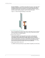
The RJ45 Input port on the power injector is wired with MDI pinouts. This means that
you must use crossover cables for connections to PCs or servers, and straight-through
cable for connections to switches or hubs. However, when connecting to devices that
support automatic MDI/MDI-X pinout configuration, you can use either straight-through
or crossover cable.
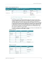
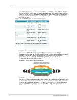
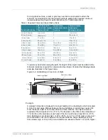
Straight-Through Wiring
Because the 10/100 Mbps Input port on the power injector uses an MDI pin
configuration, you must use “straight-through” cable for network connections to hubs or
switches that only have MDI-X ports. However, if the device to which you are
connecting supports automatic MDI/MDI-X operation, you can use either
“straight-through” or “crossover” cable.
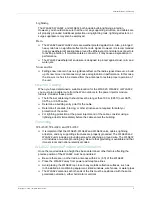
Figure 5–2. Straight-Through Cable Wiring
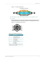
Crossover Wiring
Because the 10/100 Mbps port on the power injector uses an MDI pin configuration, you
must use “crossover” cable for network connections to PCs, servers or other end nodes
that only have MDI ports. However, if the device to which you are connecting supports
automatic MDI/MDI-X operation, you can use either “straight-through” or “crossover”
cable.
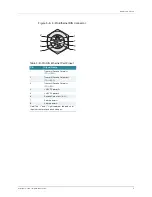
Table 1: 10/100BASE-TX MDI and MDI-X Port Pinouts
Pin
MDI-X Signal Name
MDI Signal Name
1
Receive Data plus (RD+) Transmit Data plus
(TD+)
2
Receive Data minus
(RD-)
Transmit Data minus
(TD-)
3
Transmit Data plus
(TD+)
Receive Data plus (RD+)
6
Transmit Data minus
(TD-)
Receive Data minus
(RD-)
4,5,7,8
Not used
Not used
1
Receive Data plus (RD+) Transmit Data plus
(TD+)
2
Receive Data minus
(RD-)
Transmit Data minus
(TD-)
Note: The “+” and “-” signs represent the polarity of the wires that make up
each wire pair.
White/Orange Stripe
Orange
White/Green Stripe
Green
1
2
3
4
5
6
7
8
1
2
3
4
5
6
7
8
EIA/TIA 56
8
B RJ-45 Wiring Standard
1
0/
1
00BASE-TX Straight-through Cable
End A
End B
Blue
White/Blue Stripe
Brown
White/Brown Stripe