Installing and Connecting an Access Point
34
Copyright © 2012, Juniper Networks, Inc.
Checking the LED Indicators
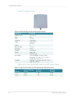
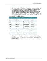
The WLA632 has LEDs that provide status information for the device. The table below
lists the function of the LEDs.
The LEDs are also used to indicate RSSI signal level during mesh link calibration.
Connecting a WLA to an WLC
You can connect an WLA directly to an WLC or indirectly to the WLC through an
intermediate Layer 2 or Layer 3 network. If you are connecting the WLA directly to an
WLC, use the following procedure to insert the cable into the WLC and verify the link.
You can use the CLI or RingMaster to configure a WLA connection. If you are installing
the WLA632 as a Mesh WLA in a WLAN Mesh or wireless bridge configuration, you
must configure the WLA connection before deploying the WLA632 in its final location.
1.
Insert a Cat 5 cable with a standard RJ45 connector. For connection to a WLA, use
a straight-through cable.
2.
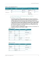
When the link is activated, observe the WLA LED for the port on the WLC:
Table 4: LED Functions
LED
Appearance
Meaning
Health
Solid green
All the following are true:
Management link with an WLC is operational.
WLA has booted.
WLA has received a valid configuration from an WLC.
At least one radio is enabled or is in sentry mode.
Solid amber
WLA is waiting to receive boot instructions and a configuration
file from an WLC.
Alternating green and amber
WLA is booting and receiving a configuration file from an WLC.
After the WLA boots and receives a configuration, this LED
appearance persists until a radio is enabled or is placed in sentry
mode.
Radio 1/ Radio 2
Solid green
A client is associated with the radio.
Blinking green
Associated client is sending or receiving traffic.
Blinking amber
Non-associated client is sending or receiving traffic.
Alternating green and amber
Radio is unable to transmit. This state can occur due to any of the
following:
Excessive radio interference in the environment is preventing
the radio from sending beacons.
DFS has detected radar and is restricting traffic.
The radio has failed.
Unlit
Means one of the following:
Radio is disabled and active scan is enabled. (The radio is in
sentry mode.)
Radio is enabled, but no clients are associated with it.
Informational Note:
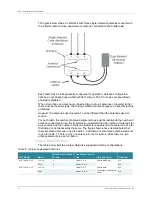
For lightning protection at the power injector end of the cable, use a
lightning arrestor immediately before the cable enters the building.


