Copyright © 2012, Juniper Networks, Inc.
13
WLA Series Technical Specifications
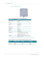
WLA632 Mechanical and Compliance Specifications
RSSI Meter Functionality
The WLA632 supports an LED-based RSSI indicator when either radio operates in
mesh link calibration mode. When mesh link calibration is enabled, the WLA transmits
calibration packets and WLAs that can receive these packets use LED patterns to
indicate the RSSI level of received calibration packets (the WLA620 must be connected
to an external RSSI meter to measure RSSI levels). Each RSSI level represents about
a 5dBm range. It is recommended to enable the link calibration on the Portal and align
the Mesh WLA antenna to have the highest RSSI levels. The RSSI reading must be
able to support the indication of received signal levels across a 35dB dynamic range,
from a high of -60 dBm to a low of -95 dBm.
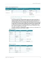
The RSSI is indicated by on/off/flashing LED patterns, as shown in the table below. The
granularity varies between 2dBm, 3dBm, and 6dBm.
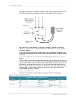
ANT-77555-OUT
2.4GHz
1
Conn 1,2, & 3
Dual-band,
Tri element, Directional
Panel
3x3
5GHz
1
Conn 4,5, & 6
3x3
ANT-5007-OUT
5GHz
1
Conn 4 & 6
Single-band,
Dual-element,
Directional Panel
2x3
Table 11: Juniper Supported Antennas
ANT Model
Band
Number of Antennas
in Use
Connector Ports in
Use
Antenna Type
11n Mode
Table 12: 5G Ch.36
LED 1
LED 2
LED 3
RSSI
Off
Off
Off
No signal
Flashing Slow
Off
Off
Very low signal
Flashing Fast
Off
Off
On
Off
Off
On
Flashing Slow
Off
Low signal
On
Flashing Fast
Off
On
On
Off
Operational signal
On
On
Flashing Slow
On
On
Flashing Fast
On
On
On
Strong signal
Table 13: 2.4G Ch.13
LED 1
LED 2
LED 3
RSSI
Off
Off
Off
No signal
Flashing Slow
Off
Off
Very low signal
Flashing Fast
Off
Off
On
Off
Off
On
Flashing Slow
Off
Low signal
On
Flashing Fast
Off


