– 55 –
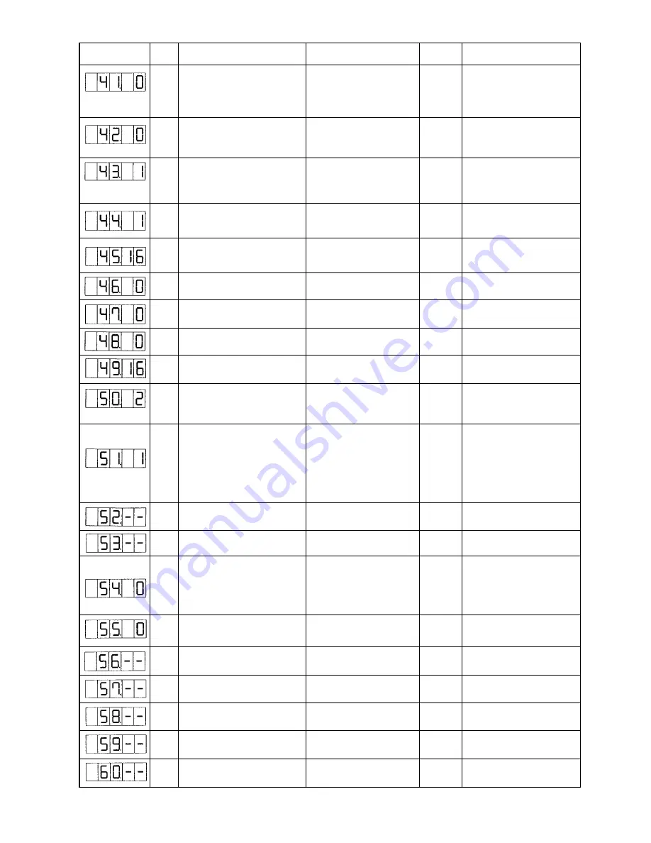
Indication
Level
Functions
Setting range
Remarks
U
State of work clamp foot when
0: Work clamp foot goes up.
0
machine stopped by temporary
1: Work clamp foot goes up
stop command can be selected.
with work clamp foot switch.
2: Lift of work clamp foot is
prohibited.
U
Needle bar stop position is set.
0: Up position (53
°
)
0
Needle bar rotates the reverse
1: Upper dead point (22
°
)
direction after the UP position stop
and stops when upper dead point
stop is set.
S
Selection of sewing machine
0:400rpm
1
This is the sewing machine rpm of the
rpm during thread trimming
1:800rpm
thread spreading by moving knife.
When the sewing machine has
stopped, thread trimmer is function.
S
Selection of whether the thread
0: Feeding disabled.
1
is moved in the direction of easy
1: Feeding enabled.
trimming.
S
Needle hole guide diameter when
16~40
16
When the setting value is increased,
feeding is moved for thread cutting. (1.6mm~4.0mm)
(1.6mm)
the amount of feeding becomes larger.
(Setting possible in the unit of 0.2mm)
U
Thread trimming can be disabled
0: Normal
0
After tentative stoppage, thread
at the end of sewing.
1: Thread trimming disabled
trimming is not disabled.
S
Thread trimming can be disabled.
0: Normal
0
All thread trimming operation is
1: Thread trimming disabled
disabled.
U
The origin reset route can be
0: Linear reset
0
selected with the reset key.
1: Pattern returning
U
Bobbin winding speed can be set
800~2000rpm
1600
(Setting possible in the unit of 100rpm)
U
Operation timing of material
0: Output prohibited
2
For the machines other than
closing is selected.
1: Operation when work clamp foot
LK-1901A, this function is not
(LK1901A only)
comes down.
indicated.
2: Operation at the time of start
U
Wiper operation method can be
0: Without wiper at the time of
selected.
thread trimming on the way
1: With wiper at the time of
1
1
Without return of the last wiper
thread trimming on the way
2
With return of the last wiper
1
(When the setting No. 37:1 of the
2: With wiper at the time of th-
memory switch, wiper operation
read trimming on the way
2
method can not be used.)
3: Magnet wiper
S
Magnet wipe-out time
10~500ms
50
Effective only if the magnet
(Setting possible in the unit of 10ms)
wiper has been selected.
S
Magnet wipe-in time
10~500ms
100
(Setting possible in the unit of 10ms)
S
Wipe-out timing at the time of
0: Sewing machine returned
0
Effective only if upper dead
upper dead point stop
and upper dead point stop
point stop is selected.
after wiper operation in up
position.
1: Wiper operation after upper
dead point stop
U
The stitching at the start of sewing 0: The stitching effective
0
For the machines other than LK-
of the pattern for button sewing
1: Tie stitching ineffective
1903A, thus function is not indi-
can be prohibited. For LK-1903A only
cated.
S
Moving limit range in +X direction
–20~20mm
20
In the state of shipment, no clamp
(right side)
configuration is considered.
S
Moving limit range in –X direction
–20~20mm
–20
In the state of shipment, no clamp
(left side)
configuration is considered.
S
Moving limit range in +Y direction
–20~10mm
10
In the state of shipment, no clamp
(back side)
configuration is considered.
S
Moving limit range in –Y direction
–20~10mm
–20
In the state of shipment, no clamp
(front side)
configuration is considered.
S
Jump feed speed of XY
100~4000pps
2000
(Setting possible in the unit of 10pps)
State when
deivered
Summary of Contents for LK-1900A
Page 20: ... 16 10 Hook adjustment Standard Adjustment 0mm 0mm 7 5mm 0 05 0 1mm For DPX5 For DPX17 ...
Page 90: ... 86 Grease Grease Grease Grease Grease 8 Needle thread clamp mechanism area ...
Page 91: ... 87 Grease Grease A Grease Grease Grease Grease 9 LK 1901A relations ...
Page 92: ... 88 10 LK 1903A relations Grease Grease ...
Page 114: ... 111 12 Circuit diagrams 1 Block diagram A ...
Page 115: ... 112 2 Power supply circuit diagram A ...
Page 116: ... 113 3 Power supply circuit diagram B ...
Page 117: ... 114 4 Power supply circuit diagram C ...
Page 118: ... 115 5 Servo motor circuit diagram ...
Page 119: ... 116 6 Sensor pedal VR circuit diagram ...
Page 120: ... 117 7 MAIN PANEL board circuit diagram ...
Page 121: ... 118 8 Motor solenoid circuit diagram Thread trimmer Lifting the work clamp foot motor ...


