– 46 –
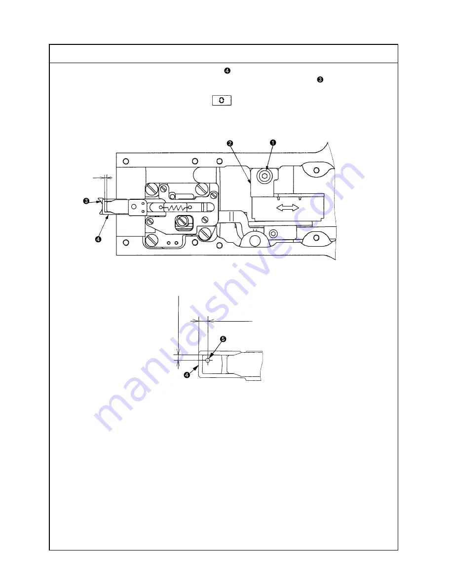
(36) Adjusting the needle thread clamp sensor
Standard Adjustment
When the needle thread clamp support plate complete
is withdrawn by 3 to 4 pulses from the needle thread
clamp position (Caution) 1., the clearance A toward the needle thread clamp device
becomes 0.
(Caution) 1. The needle thread clamp position is known to be the one that is one step returned from the
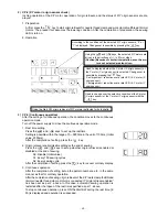
most advanced position when the key is pressed in the test mode CP-7.
3~4mm
1.7~2.3mm
C
B
A
Summary of Contents for LK-1900A
Page 20: ... 16 10 Hook adjustment Standard Adjustment 0mm 0mm 7 5mm 0 05 0 1mm For DPX5 For DPX17 ...
Page 90: ... 86 Grease Grease Grease Grease Grease 8 Needle thread clamp mechanism area ...
Page 91: ... 87 Grease Grease A Grease Grease Grease Grease 9 LK 1901A relations ...
Page 92: ... 88 10 LK 1903A relations Grease Grease ...
Page 114: ... 111 12 Circuit diagrams 1 Block diagram A ...
Page 115: ... 112 2 Power supply circuit diagram A ...
Page 116: ... 113 3 Power supply circuit diagram B ...
Page 117: ... 114 4 Power supply circuit diagram C ...
Page 118: ... 115 5 Servo motor circuit diagram ...
Page 119: ... 116 6 Sensor pedal VR circuit diagram ...
Page 120: ... 117 7 MAIN PANEL board circuit diagram ...
Page 121: ... 118 8 Motor solenoid circuit diagram Thread trimmer Lifting the work clamp foot motor ...


