


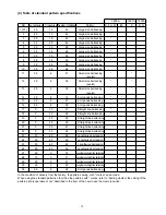


– 71 –
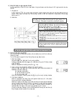
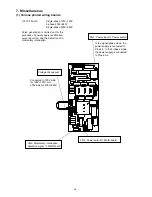
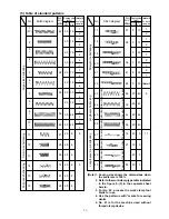
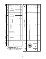
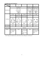
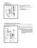
(2) LK1900 data ROM
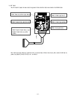
The data ROM for the LK-1900 is used by inserting it in
the IC socket that is located on the MAIN board.
(Cautions) 1. Pay attention to the direction of inser-
tion.
2. EEPROM cannot be used.
3. If the pattern number is the same as
that of the standard pattern, the pat-
tern in the data ROM is in higher pref-
erence.
Available ROM
27C256 EPROM
JUKI part No.: HL008423000
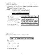
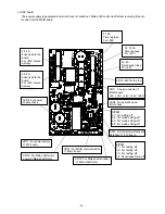
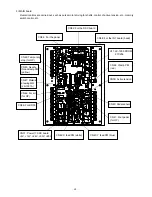
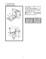
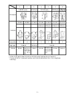
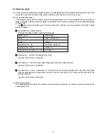
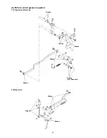
(3) Dipswitch setting
1. The penetration force is increased when “4” of
Dipswitch SW1
is turned ON on the SDC board
.
2. If the penetration force is insufficient for thick materi-
als, this switch should be turned ON.
3. All other dipswitches should be turned OFF.
(Caution) Dipswitch changeover should be done af-
ter the power supply has been turned off.
4. All dipswitches on the MAIN board are turned OFF.
SDC board
MAIN board
SW1
SW2
SW3
Summary of Contents for LK-1900A
Page 20: ... 16 10 Hook adjustment Standard Adjustment 0mm 0mm 7 5mm 0 05 0 1mm For DPX5 For DPX17 ...
Page 90: ... 86 Grease Grease Grease Grease Grease 8 Needle thread clamp mechanism area ...
Page 91: ... 87 Grease Grease A Grease Grease Grease Grease 9 LK 1901A relations ...
Page 92: ... 88 10 LK 1903A relations Grease Grease ...
Page 114: ... 111 12 Circuit diagrams 1 Block diagram A ...
Page 115: ... 112 2 Power supply circuit diagram A ...
Page 116: ... 113 3 Power supply circuit diagram B ...
Page 117: ... 114 4 Power supply circuit diagram C ...
Page 118: ... 115 5 Servo motor circuit diagram ...
Page 119: ... 116 6 Sensor pedal VR circuit diagram ...
Page 120: ... 117 7 MAIN PANEL board circuit diagram ...
Page 121: ... 118 8 Motor solenoid circuit diagram Thread trimmer Lifting the work clamp foot motor ...