


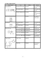
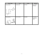
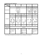
– 63 –
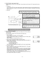
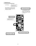
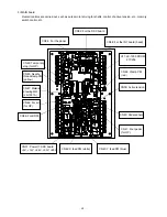
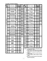
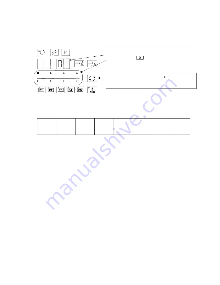
Pattern LED X enlarge LED Y enlarge LED Speed LED Counter LED Bobbin winder LED Threading LED Tension LED
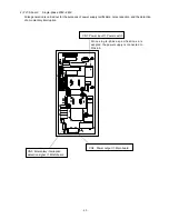
MAIN board
MAIN board
MAIN board
MAIN board
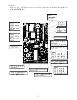
SDC board
SDC board
SDC board
SDC board
RR
VV
LL
xx
RR
VV
LL
xx
RR-VV-LL-xx display for the MAIN and SDC boards for each item selection LED
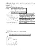
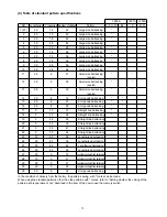
8) CP-8 (Software version display)
The software versions of the MAIN and SDC boards are displayed.
Each version comes in the type description of RR-VV-LL-xx. “xx” is used for the specifications of special order-
ing. It is not displayed usually.
(Example: 01-01-01, 01-01-02, 01-02-01)
1. Operation
Display changeover is possible with the key in the order of
RR
→
VV
→
LL
→
(xx)
→
for the MAIN board and RR
→
VV
→
LL
→
(xx)
→
for the SDC board.
According to the item selection LED, RR-VV-LL-xx of the MAIN
and SDC boards is respectively displayed. Changeover is pos-
sible by pressing the key. Contents of the display are shown
in the table below.
Summary of Contents for LK-1900A
Page 20: ... 16 10 Hook adjustment Standard Adjustment 0mm 0mm 7 5mm 0 05 0 1mm For DPX5 For DPX17 ...
Page 90: ... 86 Grease Grease Grease Grease Grease 8 Needle thread clamp mechanism area ...
Page 91: ... 87 Grease Grease A Grease Grease Grease Grease 9 LK 1901A relations ...
Page 92: ... 88 10 LK 1903A relations Grease Grease ...
Page 114: ... 111 12 Circuit diagrams 1 Block diagram A ...
Page 115: ... 112 2 Power supply circuit diagram A ...
Page 116: ... 113 3 Power supply circuit diagram B ...
Page 117: ... 114 4 Power supply circuit diagram C ...
Page 118: ... 115 5 Servo motor circuit diagram ...
Page 119: ... 116 6 Sensor pedal VR circuit diagram ...
Page 120: ... 117 7 MAIN PANEL board circuit diagram ...
Page 121: ... 118 8 Motor solenoid circuit diagram Thread trimmer Lifting the work clamp foot motor ...