2 – 3
2.1
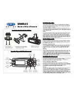
Operation controls and keys
Those preceded by a number enclosed in a box are the controls and keys used with ATA model NCA-843.
z
[SUB MENU] key
Displays the sub menu on the screen.
x
[MAIN MENU] key
Displays the main menu on the screen.
e
Trackball
Moves the cursor to a desired position.
r
/
t
[
−
−
−
−
−
] and [
+
+
+
+
+
] keys
Select the range between 0.125 and 96/120 nautical mile.
y
[TUNE] control
Controls the target on the screen to be seen most clearly.
u
[GAIN] control
Controls the receiving sensitivity of the radar.
i
[RAIN] control
Decreases clutter videos due to rain or snow.
o
[SEA] control
Decreases clutter videos due to reflection from the sea surface.
!0
[BRILL] control
Adjusts the brilliance of the display.
⁄1
[COLOR] control
Sets the color for the own and other ship tracks, marks and lines.
(7 colors: white, sky, blue, green, yellow, pink and red)
!2
[FUNC] key
Selects the pre-set video processing
⁄3
[GZ MENU] key
Displays the menu for setting an alarm.
!4
[MAP] key
Switches the system to the radar, composite or plotter mode.
!5
[AZI MODE] key
Switches the screen to the true bearing, relative bearing, course-up or stabilized course-up mode.
!6
[HL OFF] key
The HL (Heading Line) can be cleared while this switch is being pressed.
Summary of Contents for JMA-7710-6
Page 1: ......
Page 2: ......
Page 20: ...XVIII ...
Page 22: ......
Page 30: ...1 7 1 4 Fig 1 2 Outline Drawing of Scanner Unit Type NKE 1056 6M MASS APPROX 41 O UNIT mm ...
Page 31: ...1 1 8 1 4 Fig 1 3 Outline Drawing of Scanner Unit Type NKE 1056 9M MASS APPROX 47 O UNIT mm ...
Page 34: ...1 11 1 5 Fig 1 5 General System Drawing of Radar Type JMA 7710 6 ...
Page 35: ...1 12 1 5 1 Fig 1 6 General System Drawing of Radar Type JMA 7725 6 ...
Page 36: ...1 13 1 5 Fig 1 7 General System Drawing of Radar Type JMA 7725 9 ...
Page 48: ...2 7 2 1 Screen Readouts 3 1 2 3 4 5 7 u i o y 1 0 q 2 t w e r 0 8 4 5 6 7 8 9 0 9 6 ...
Page 50: ...2 9 2 1 Screen Readouts with ATA 3 1 2 3 4 5 7 u i o y 1 0 q 2 t w e r 8 4 5 6 7 8 9 0 9 6 ...
Page 99: ...3 3 38 3 3 ...
Page 164: ......
Page 208: ......
Page 216: ......
Page 217: ...7 7 1 Routine Maintenance 7 1 7 2 Maintenance of Each Unit 7 2 MAINTENANCE ...
Page 222: ......
Page 276: ......
Page 277: ...9 AFTER SALES SERVICE ...
Page 280: ......
Page 294: ......
Page 298: ...Appendix 2 Circuit Diagram of Radar Type JMA 7710 6 and JMA 7725 6 9 ...
Page 299: ...Appendix 3 Terminal Board Connection Diagram of Radar Type JMA 7710 6 ...
Page 300: ...Appendix 4 Terminal Board Connection Diagram of Radar Type JMA 7725 6 9 ...
Page 301: ...Appendix 5 Primary Power Supply System Diagram of Radar Type JMA 7710 6 and JMA 7725 6 9 ...
Page 302: ...Appendix 6 Internal Connection Diagram of Scanner Unit Type NKE 1055 ...
Page 303: ...Appendix 7 Internal Connection Diagram of Scanner Unit Type NKE 1056 ...
Page 304: ...Appendix 8 Internal Connection Diagram of Display Unit Type NCD 3901 2 ...
Page 308: ...Appendix 10 NSK Log Selection Switches of Display Unit Type NCD 3901 2 ...
Page 309: ...Appendix 11 Setting Table of the Speed Log Select Switches of Display Unit Type NCD 3901 2 ...
Page 312: ......
Page 313: ......
Page 314: ......


