VYPER
™
VARIABLE SPEED DRIVE
INSTALLATION
S100-200 IOM (MAY 08)
Page 27
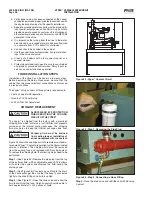
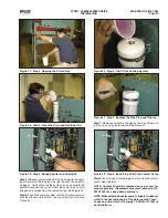
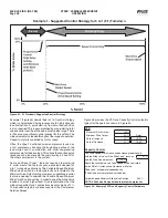
Figure 27 - Step 3, Opening the Drain Valve
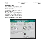
Figure 28 - Step 4, Close the Drain and Refi ll the Unit
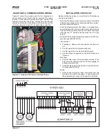
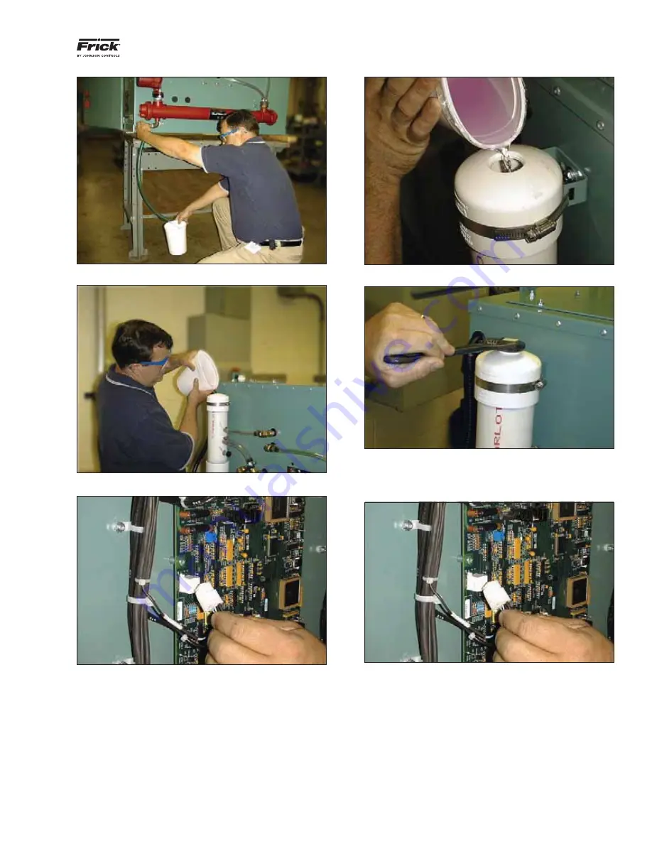
Figure 29 - Step 5, Reapply power and Unplug J2
Step 5:
Reapply power to the VSD unit and locate the Logic
Board found on the inside of the right door on the cabinet.
Unplug J2, which will cause the pump to run and circulate the
coolant throughout the system. Allow the pump to run until all
trapped air is purged from the coolant system. See Figure 29.
Step 6:
Top off the cooling system until the fl uid level remains
constant about one inch form the top of the manifold. See
Figure 30.
Figure 30 - Step 6, Top Off the Cooling System
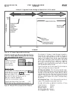
Figure 31 - Step 7, Replace the Pipe Plug and Tighten
Step 7:
Replace and tighten the plug on the top of the mani-
fold using an adjustable wrench. See Figure 31.
Figure 32 - Step 8, Insert Plug J2 to Stop Coolant Pump
Step 8:
Insert plug J2 into the logic board to stop the coolant
pump. See Figure 32.
NOTE: Coolant should be replaced once per year for
proper operation. (Replacement coolant number is 013-
02987-000 for a one gallon container)
NOTE: When adding a booster pump to supply condenser
water to the heat exchanger of the water cooled Vyper
™
,
choose a pump which will supply 10 GPM at 15 feet of
head minimum.

