VYPER
™
VARIABLE SPEED DRIVE
MAINTENANCE
S100-200 IOM (MAY 08)
Page 48
12. Insert the (8) Allen head screws through the new IGBT
module and engage a few threads in the chill plate, but
DO NOT
tighten. The new Vyper
™
power module should
still be loose.
13. Align the Vyper
™
power module so that the (6) Phillips head
screws can be installed through the bus structure and into
the IGBT module.
DO NOT
tighten these screws.
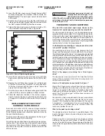
14. Tighten the Allen head screws to 48 in-lb (5.5 Nm) ±10%
in the numerical sequence shown in Figure 58.
Figure 58 - Screw Tightening Sequence
15. Install the (3) power wire connector tabs using (6) Phillip
head screws and torque the screws to 48 in-lb (5.5 Nm)
±10%.
16. Remove the (6) Phillips head screws (not yet tightened)
at the bus structure and install the 3 square capacitors
to the bus structures with the these screws. Torque the
screws to 48 in-lb (5.5 Nm) ±10%.
17. Close the drain valve on the heat exchanger and refi ll the
system with the coolant supplied and check for leaks.
18. Follow the directions included in the start-up prepara-
tions for running the Vyper’s circulation pump to ensure
all trapped air is vented and the coolant loop is properly
fi lled.
REPLACEMENT OF THE VYPER
™
HARMONIC FILTER MODULE
Personnel not familiar with AC drive and proper electrical
safety guidelines should not be working on this product.
Power module replacement should be performed only by
Frick certifi ed technicians.
The procedure is the same as the replacement for the Vyper
™
power module except for the following.
Drain the coolant as described in the power module replace-
ment section. Then remove one of the coolant hoses feeding
the Harmonic Filter Power Module. Failure to completely
drain the coolant system will cause coolant to leak into the
VSD enclosure.
Untrained personnel should not
attempt to service the Vyper
™
vari-
able speed drive. Electrical levels
within the unit can cause serious injury or death. Please
call Johnson Controls-Frick for trained service personnel
to work on your unit.
FREQUENTLY ASKED QUESTIONS
Why don’t the measured input amps shown on the
Quantum
™
LX control panel agree with the rated FLA?
The input current to the Vyper
™
may be considerably lower
compared to the output current. This is due to the power factor
at the input to the Vyper
™
being greater than 0.95 and nearly
unity when the Harmonic fi lter option is included. Motor FLA
must be measured at the motor terminals, where the power
factor is the normal motor power factor. Use the true RMS
reading meter to make the measurements.
On the Remote-mounted Vyper
™
compressor drive, what
is the dV/dt “snubber” fi lter for?
The combination of long runs of wire between the Frick
Vyper
™
and the compressor motor with the fast rise time of
the output voltage of the Vyper
™
can cause excessively high
voltage potential at the motor terminals. Without the dV/dt fi l-
ter, the insulation in the motor terminal can be overly stressed.
The dV/dt network reduces the high voltage motor potential
to below the motor’s voltage specifi cation. The design of the
dV/dt network has a requirement to be added to the top of the
motor terminal box. No additional wire may be added between
the dV/dt network and the motor terminal connections. The
addition of wire reduces the dV/dt network’s effectiveness
and potentially shortens the life of the motor.
What is the proper wire sizing for a Frick Vyper
™
drive?
The input power wires are sized at 1.25 times the full load
amps of the compressor motor, plus oil pump amps and
control transformer amps.
How is a 12-lead motor connected to the Vyper
™
?
Most of the 12 lead motors actually have two sets of parallel
windings, and therefore have two ones, two twos, etc. The
Vyper
™
is connected to the motor in the delta confi guration
which means that leads are paired 1 and 6, 2 and 4, and 3
and 6. The T1 lug in the Vyper
™
will then have two ones and
two 6s attached to it.
Some motors, which were produced in the past, were labeled
as 1 through 12. These motors had the fi rst set of wires
marked 1 to 6. Numbering then continued with the second
1 marked as 7, 2 numbered as 8, so on up to twelve. Take
the second set of numbers above six, subtract 6 from the
number and relabel the result.
What is the peak input voltage value?
The displayed value is the phase to neutral voltage at the
input to the drive in terms of peak voltage, as measured by
an oscilloscope.
Phase to neutral is normally the phase-to-phase voltage
divided by the square root of three, or 265 VAC phase to
neutral, for a 460 VAC system. The peak value of the 265 VAC
measurement is approximately that number times the square
root of two.

