VYPER
™
VARIABLE SPEED DRIVE
OPERATION
S100-200 IOM (MAY 08)
Page 31
Clear VSD Memory:
Clear the existing trending values in
the Vyper
™
memory.
Clear Total kWh:
This function clears the accumulated kWh
totals from the counter since the last reset. The value returns
to zero upon selecting this option.
The following Vyper
™
screen parameters display measured
values in accordance with the user defi ned unit selections.
•
Average Current (Amps)
•
Current Phase A (Amps)
• Current Phase B (Amps)
• Current Phase C (Amps)
•
Full Load Amps (%)
•
Output Frequency (Hz)
•
Output Voltage (Volts)
•
DC Bus Voltage (Volts)
•
Input Power (kW)
•
Current Value Timer (Min:Sec)
•
Actual Speed (RPM)
•
Speed Command (RPM)
•
Ambient Temperature (°F or °C)
•
Converter Heatsink Temp (°F or °C)
•
Base plate Temperature (°F or °C)
•
Job FLA (Amps)
•
DC Inverter Link Current (Amps)
•
Motor Temperature (°F or °C)
• VSD Model (305 or 437)
•
Total kWh (kWh)
The following parameters indicate the status of the fi eld.
They are displayed as the following:
“0” - no /off “1” - yes / on
• VSD Operating Mode
•
Harmonic Filter Present
•
Harmonic Filter Operating Mode
• Water Pump Energized
• Precharge Relay Energized
• Trigger SCRs Energized
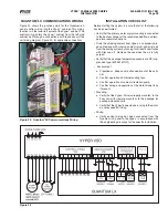
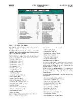
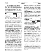
HARMONIC FILTER SCREEN
The Harmonic Filter screen (See Figure 37) shows important
aspects of the IEEE519 Harmonic Filter in action. In addi-
tion to current and voltage information it also provides the
important measure of current THD.
All IEEE 519 Harmonic fi lter parameters are displayed on
this page. This information is useful to obtain the status,
operating conditions and diagnostic information for the
Harmonic Filter.
The following parameters display a real value based on the
displayed units:
•
Total Harmonic Distortion Leg,1,2,3 ( %)
•
Total Demand Distortion Leg 1,2,3 (%)
•
Filter Current Leg 1,2,3 (Amps)
•
Supply Current Leg 1,2,3 (Amps)
• Voltages L1-N, L2-N, L3-N,
• L1-L2, L2-L3, L3-L1 (Voltage)
• Total Supply kVA (kVA)
• Total Power Factor (%)
• Base plate Temperature (°F or °C)
• DC Bus Voltage (Volts)
•
Manual Speed Switch Status (RPM)
Figure 37 - Harmonic Filter Screen

