VYPER
™
VARIABLE SPEED DRIVE
INSTALLATION
S100-200 IOM (MAY 08)
Page 10
fi elds, which are transmitted through the air. EMI refers to
electrical currents, which are conducted in wiring connected
to the device.
The Vyper
™
generates both RFI and EMI. Most RFI energy
generated by Vyper
™
is contained within it’s cabinet. The EMI
energy is conducted back in to the power line, and may be
capable of causing interference to other electronic equipment
that is powered by the same electrical distribution system.
VSDs are used successfully in many installations, which uti-
lize sensitive electronic equipment. However, in some highly
sensitive cases, there may be electronic equipment that is
affected by Vyper
™
originated EMI. For those cases, an op-
tional Harmonic Filter is recommended to reduce conducted
EMI levels by reducing current harmonics to limits defi ned by
the IEEE 519-1992 standard. The fi lter is located within the
Vyper
™
cabinet and is factory installed and tested. The fi lter
can also be retrofi tted to an existing Vyper
™
.
The IEEE 519 fi lter is required on all hospital applications, and
is strongly recommended for any installation with sensitive
electronic equipment connected to the electrical distribution
system. The fi lter is also required whenever a local utility
places a limit on current distortion for an electronic device.
The IEEE 519 harmonic fi lter is fi lter is required where total
harmonic current distortion must be 8% or less.
SYSTEM OPERATING CONDITIONS
Refrigeration systems considered for Vyper
™
application
must be in good operating condition. A site survey should be
completed with the help of a trained Frick service technician.
The technician will review the condition of the equipment and
recommend actions that must be taken to ensure that the
equipment is in good operating condition. This survey must
be taken and required repairs made prior to the application
of the Vyper
™
.
PNEUMATIC CONTROLS
Pneumatic controls must be replaced with electronic controls
to be compatible with the Vyper
™
and the Quantum LX
™
control panel.
VYPER
™
SYSTEM OVERVIEW
The Frick Vyper
™
Variable Speed Drive is a liquid-cooled,
transistorized, PWM inverter in a highly integrated package.
This unit is factory designed to mount either remotely on a
stand or integrally to the compressor package. The power
section of the drive is composed of four major blocks:
• AC to DC rectifi er section with integrated precharge circuit
• DC link fi lter section
• Three-phase DC to AC inverter section
• Output suppression network
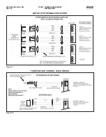
An electronic circuit breaker with ground fault sensing con-
nects the AC line to an AC line choke and then to the DC
converter. The line choke will limit the amount of fault current
so that the electronic circuit breaker is suffi cient for protecting
the Vyper
™
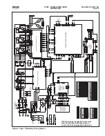
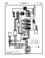
input fuses. (See schematic, Figure 8)
THE AC TO DC SEMI-CONVERTER
uses 3 Silicon Con-
trolled Rectifi ers (SCRs) and 3 diodes. One SCR and one
diode are contained in each module. Three modules are
required to covert the three-phase input AC voltage to DC
voltage (1SCR-3SCR). The modules are mounted on a liquid-
cooled heatsink. The use of the SCRs in the semiconverter
confi guration permits precharge of the DC fi lter link capacitors
when the chiller enters the prelube cycle. It also provides fast
disconnect from the AC line. The SCR trigger board provides
the turn on and turn off commands for the SCRs. The Vyper
™
logic board provides commands to the SCR trigger board
during precharge.
THE DC LINK FILTER SECTION
of the drive consists of a
series of electrolytic fi lter capacitors (C1-C6). These capaci-
tors provide a large energy reservoir for use by the DC to
AC inverter section of the Vyper
™
. The capacitors are con-
tained in the Vyper
™
Power Unit. “Bleeder” resistors (RES1
and RES2) are mounted on the side of the Power Unit to
provide a discharge of the DC Link fi lter capacitors after
power is removed.
THE DC TO AC INVERTER SECTION
of Vyper
™
serves
to convert the DC voltage back to AC voltage at the proper
magnitude and frequency as commanded by the Logic
board. The inverter section is composed of one power unit.
This power unit is composed of very fast switching transis-
tors known as an Insulated Gate Bipolar Transistor (IGBT)
module (1MOD) mounted on the same liquid-cooled heatsink
as the semiconverter modules, the DC Link fi lter capacitors
(C1-C6), a semiconverter, and a Vyper
™
Gate Driver board.
This board provides the turn on, and turn off commands
to the IGBT’s output transistors. The Vyper
™
Compressor
Drive Logic board determines when the turn on, and turn off
commands should occur. The gate driver board is mounted
directly on top of the IGBT module, and it is held in place with
mounting screws and soldered to the module. This improves
reliability by eliminating the gate wires and their possible
failure. In order to minimize the parasitic inductance between
the IGBT module and the capacitor bank, copper plates which
electrically connect the capacitors to one another and the
IGBT modules are connected together using a “laminated
bus” structure. This “laminated bus” structure forms a parasitic
capacitor which acts as a low valued capacitor, effectively
canceling the parasitic conductance of the copper plates. To
further cancel parasitic inductances, a series of small fi lm
capacitors (C7-C9) are connected between the positive and
negative plates at the IGBT module.
THE VYPER
™
OUTPUT SUPPRESSION NETWORK
is
composed of a series of capacitors (C10-C12) and resistors
(3RES-8RES). The job of the suppressor network is to reduce
the time it takes for the output voltage to switch as seen by
the motor. It also limits the peak voltage applied to the mo-
tor windings, as well as the rate of change of motor voltage.
These are problems commonly associated with PWM motor
drives such as stator winding end turn failures and electrical
fl uting of motor bearings.
Other sensors and boards are used to convey information
back to the Vyper
™
and provide safe operation of the variable
speed drive. The IGBT transistor module contains a thermis-
tor temperature sensor that provides temperature information
back to the logic board via the gate driver board. The AC to
DC semiconverter heat sink temperature is also monitored
using a thermistor temperature sensor (RT2). The uses the
three resistors on the board to provide a safe impedance
between the DC link fi lter capacitors located on the power
unit and the logic board. This provides the means to sense
the positive, midpoint, and negative voltage connection points
of the VSD’s DC Link. Three current transformers (3T-5T)
monitor the output current from the Vyper
™
power unit and
are used to protect the motor from over-current situations.


