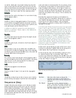
ROTOR PARAMETERS (MOD MODE)
26 | ROTORS 1-2
Parameter
Description
LinFM
Linear frequency modulation of the oscillator,
in percentage.
Shape
Shape of the oscillator waveform (or detuning
spread of the Jaws waveform), in percentage.
Table 3. Oscillator 1-4 Modulation Destinations
Rotors 1-2
Solaris has 2 Rotor processors. There are four inputs to
each Rotor. Each is presented at the Rotor’s output in
series, one after the other. You can think of it as a four-step
wave sequence, where each step’s sound comes from
one of the many sound sources in Solaris. The
X-Fade
(cross fade) control ‘smooths’ the transition from one step
to the next, and does it uniformly for all four inputs. If the
X-Fade
amount is zero, then the transition from one step
to the next will be abrupt; at full amount (127), each step is
cross faded with the next, providing smooth but constant
changes in the output. When the Rotor runs at audio rates,
the transitions happen so quickly that we hear the results
as a unique waveshape itself – one can change either
the coarse and fine tunings of each input, or the source
material itself to create timbre changes. You will also find
that at audio rates, the
X-fade
amount makes the wave-
form less bright as you move from zero to max amount, as
the smoothing function takes off the ‘rough edges’ of the
resultant as it is increased. One unusual way of generat-
ing new harmonic structures is to run the Rotor at audio
rates, tracking the keyboard. This is almost like a granular
approach in that you will hear small bits of each input at a
rapid rate.
Rotor Parameters (Main Mode)
Rotor
Main
mode comprises three pages of parameters,
accessed by pressing the Inc/Dec buttons to the left of the
text display.
Page 1 Parameters
Figure 29. Rotor Main Mode, page 1
Coarse
Coarse tuning of the Rotor, between -60 and 60 semitones.
This control allows the Rotor to operate as an audio-rate
oscillator.
The Clock Sync, No Track and Low buttons on the
Oscillators panel have the same effect on the Ro-
tors as the do on the standard Oscillators Osc 1-4.
Refer to that section for an explanation of how
these buttons affect the oscillator’s frequency.
Fine
Fine tuning amount of the Rotor. Allows fine adjustments of
the Rotor’s pitch over the range or +/- 1 semitone.
X-Fade
This parameter controls the amount of cross fade applied
between each of the four steps of the Rotor processor. The
higher the value, the greater the amount of cross fade.
Sync
When Sync is set to Gate, the Phase parameter can be
used to determine at which step in the Rotor’s cycle it will
reset with each new note on event.
Phase
When Synch is set to Gate, the Phase parameter can be
used to control the starting point of the Rotor processor
when new note on events are received.
Page 2 Parameters
Figure 30. Rotor Main Mode, page 2
Inputs 1 - 4
Page 2 of the Rotors
Main
mode controls allows you to as-
sign the inputs to the Rotor’s four inputs. Typically, these in-
puts will be assigned to sound sources such as oscillators,
but they can be assigned to control signals as well, opening
the doors to expansive new modulation possibilities.
Page 3 Parameters
Figure 31. Rotor Main Mode, page 3
Rotor Parameters (Mod Mode)
The Rotors also have four independent modulation sources
available, but the destination parameters are specific to the
Rotor processors. The
Dest
options are Pitch and XFade
(cross fade amount).
Parameter
Description
None
No parameter will be modulated
Pitch
Exponential frequency modulation of the oscil
-
lator, in semitones.
XFade
Crossfade amount.
Table 4. Rotor Processor 1-2 Modulation Destinations
Clock Sync, No Track and Low
These buttons have the same function as they do with OSC
1-4. Please refer to “Clock Sync, No Track and Low” on
page 24.
Summary of Contents for Solaris
Page 1: ...User Guide Version 1 ...


