background image

80

5.5-2

5.5-1

5.5-3

5.5. Special Functions

5.5.1 Behind-the-spokes placement

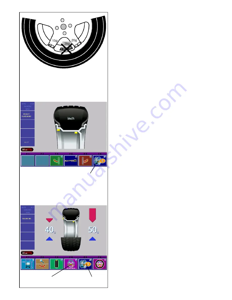
When spoked wheels (SOFT LINE rims) are balanced,
the behind- the-spokes placement mode (also called
split weight mode) allows balance weights which would
have to be fitted between two spokes according to the
measured unbalance (hence would be visible from
outside) to be placed in hidden position behind two
spokes adjacent to the unbalance location (see
example, Fig. 5.5-1).
After a measuring run the electronic unit calculates the
behind-the-spokes placement automatically and reads
the relative balance weight locations on the screen.
The pictographs guiding the operator through this mode
are explained in § 4.1.2.
The operating steps for the behind-the-spokes
placement mode are described and illustrated below.

How to proceed
Behind-the-spokes placement is activated
automatically in Alu 2, Alu 2S and Alu 3, Alu 3S
balancing modes (hidden weight) and can be selected
there whenever required.

Choice of balancing mode (weight fitting position)
Choice of behind-the-spokes placement mode and
rim data input
The behind-the-spokes placement mode is activated
with the menu key F1 in the screen 

RIM DATA INPUT

,

the number of spokes of the wheel is chosen either
with the menu key F6 in the screen WEIGHT
PLACEMENT, or with the menu key F5 in the screen
BALANCING.

In the screen WEIGHT PLACEMENT:

In the screen WEIGHT PLACEMENT press the
menu keys F3 and F5 to choose the balancing
modes Alu 2, Alu 2S, Alu 3 or Alu 3S (see § 5.3.2).

Next comes Fig. 5.5-3 with the menu key F6 and the
selected number of spokes.
The number of spokes can be chosen between 3 and
12.

Press and hold the menu key F6. Rotate the wheel
to set the number of spokes of the wheel (1, Fig.
5.5-2
).

The pictograph with the chosen number of spokes
appears in the menu field F6 (2, Fig. 5.5-3).

In the screen BALANCING (when other wheels have
been balanced before):

Press and hold the menu key F5. Rotate the wheel
to set the number of spokes of the wheel.

The pictograph with the chosen number of spokes
appears in the menu field F5 (2, Fig. 5.5-3), the menu
field “Behind-the-spokes placement“ appears in F6 (1,
Fig. 5.5-3
).

1

2

1

Summary of Contents for VPI System IV

Page 1: ...OPERATION INSTRUCTIONS Form ZEEWB516A 5872 VPI SYSTEM IV COMPUTER WHEEL BALANCER ...

Page 2: ...mensions For The Standard Balancing Mode 48 5 3 3 1 Determination And Input Of Rim Width 49 5 3 3 2 Gauge Head Application On Various Wheel Types 49 5 3 3 3 Determination Of Distance And Diameter 50 5 3 3 4 Determination And Input Of Wheel Diameter 51 5 3 3 5 Determining The Position Of The Hidden Weights Alu 2s 52 5 3 3 6 Determining The Position Of The Hidden Weight Alu 3s 53 5 3 3 7 Input Of Ri...

Page 3: ...timization Weight Minimization 88 5 5 4 1 General 88 5 5 4 2 Optimization Weight Minimization Programs 88 5 5 4 3 Start Optimization Weight Minimization 89 5 5 4 4 Start Optimization 89 5 5 4 5 Continue Minimization And Optimization 90 5 5 5 Performing A Compensation Run 93 6 Maintenance 108 6 1 Storage 108 6 2 Changing The Mains Fuse 108 6 3 Calibration Procedure 110 7 Trouble Shooting 114 7 1 Sy...

Page 4: ...1 1 ...

Page 5: ...arnings and cautions when possible dangerous situations may be encountered during the described procedures 1 1 Typography This manual contains text styles that asks you to pay extra attention Note Suggestion or explaination CAUTION STRESSES THAT THE FOLLOWING ACTION MAY CAUSE DAMAGE TO THE UNIT OR OBJECTS ATTACHED TO IT WARNING STRESSES THAT THE FOLLOWING ACTION MAY CAUSE SEVERE INJURY TO THE OPER...

Page 6: ...er Cone small Cone medium Cone large Dimensions Weight Shipping weight Dimensions hxdxw Shipping dimensions Miscellaneous Noise level 2 1 Conditions During use or long term storage the conditions should never exeed Temperature range 0 50 C Humidity range 10 90 non condensing 230 V 50 60 Hz 1 ph 0 12 kW 1 1 A 2x IEC 127 T5A IP54 3 s 200 rpm 0 400 mm 0 5 25 1 mm 530 mm 950 mm 70 kg 25 510 1 20 mm 20...

Page 7: ...on the rim That way a proper mounting of the wheel and an optimal balancing result can be reached Application The off the vehicle wheel balancer is designed for dynamic and static balancing of passenger car and light truck wheels that fall within the limits stated in the technical specifications This is a high accuracy measuring device Handle with care Manuals to the unit The setup of the informat...

Page 8: ...dard accessories are Quick Release Hub Nut Spacer ring Universal drum Universal drum cushion Large cone Medium cone Small cone Stub shaft Key User Calibration weight Weight pliers Callipers 4027007 0026425 0026426 0026427 0025539 0025518 0025517 0025516 4025821 0025415 0006452 4007580 ...

Page 9: ...hood Hood may be optional Refer to Figure 4 2 1 Mains switch ON OFF 4 1 The screen Fig 4 1 1 Screen with display fields 1 5 Information fields 6 Menu fields of screen 7 Display field of screen The screen reads out inputs helpful information all measured data and error codes Description of display fields The screen is subdivided into various display fields each of which is associated with a certain...

Page 10: ...tion dimensions no nominal size Motorcycles Program P4 Wheel type 2 standard nominal size in mm 6 Menu fields Pictographs illustrating special features are viewed in the six menu fields Under every menu field is the associated menu key which is used to call the feature illustrated 7 Display field Wheel type and rim dimensions Balancing modes Direction of orientation and correction position locatio...

Page 11: ...P21 P9 Standard rim Balancing modes P12 nor Standard balancing mode P13 Alu 1 P14 Alu 2 Alu 2P P15 Alu 3 Alu 3P P16 Alu 4 P17 Alu 5 P20 Gauge arm for distance and rim diameter P21 Gauge arm for distance and rim diameter with adhesive weight ...

Page 12: ...ction position reached green arrows P24 Correction position for both correction planes reached P25 Compensation run carried out P26 Start measuring run by pressing the START key after closing the wheel guard P27 Calibration weight P28 Main shaft P29 Select memory location for wheel profile red arrow P30 Select a previously stored wheel profile green arrow 70g 0g ...

Page 13: ...ressure P34 Turn tire over on rim P35 Rotate rim until valve is exactly perpendicular to and above the main shaft P36 Rotate wheel until valve is exactly perpendicular to and above the main shaft P37 Readjust tire on rim until the mark coincides precisely with the valve P38 Readjust tire on rim until the double mark coincides precisely with the valve P39 Tire changer ...

Page 14: ...ncing b Press and hold key down while rotating wheel at same time e g key T11 Number of spokes c Press key to toggle between two options or states e g key T9 Static dynamic unbalance d Press key to toggle between several options or states e g key T21 Weight position for left correction plane e Toggle switch 4 functions Press edge of key to carry out the highlighted action e g key T32 Character set...

Page 15: ...ion of unbalance for conventional balancing run with balance clips comes up T9 Select static unbalance T10 Select dynamic unbalance T11 Select number of spokes T12 Wheel with 6 spokes selected T13 Select behind the spokes placement mode T14 Behind the spokes placement mode selected RIM DATA INPUT T15 Change to the screen WEIGHT PLACEMENT T16 Change to the screen RIM TYPE T17 Hold key down and ente...

Page 16: ...t position for right correction plane FUNCTION T23 Change to the screen USER CALIBRATION T24 Change to the screen TEXT EDITOR T25 Hold key down and set the value for the mode of operation by rotating the wheel T26 Hold key down and select the mode of operation by rotating the wheel PROFILE T27 Confirm wheel profile to be saved or selected T28 Select stored wheel profile T29 Store wheel profile T30...

Page 17: ...thin the character set right left up down T33 Transfer characters from the character set to the text field T34 Toggle key four functions Move the cursor within the text field right left up down OPTIMIZATION WEIGHT MINIMIZATION T35 Continue interrupted optimization T36 Start MINIMIZATION T37 Confirm T38 Back ...

Page 18: ...lp information to the screen RIM DATA INPUT Fig 4 1 3 3 appears Note On pressing the HELP key in the last screen with help information the display jumps to the first screen again Quit help information Press the ESC key 2 Fig 4 1 3 1 4 1 4 Main shaft lock Fig 4 1 4 1 Pedal of main shaft lock The main shaft is locked when the pedal is depressed This facilitates tightening or untightening of the clam...

Page 19: ...een the devices and the unit Refer to the supplied technical information The method used to mount a wheel depends on the way the wheel is centered at the vehicle When the rim has a true center hole a hub centric wheel use a cone Refer to Figure 5 1 1 top This is also the faster way to mount a wheel If the correct cone is not available or if a wheel is very hard to balance using an adaptor plate ma...

Page 20: ...nge with the knurled thumbnuts provided Then mount the wheel using the normal front cone method Double Cone Mounting The cones must not touch each other If the cones touch the wheel will not be centred and mounted securely Note Double cone mounting can be used for some speciality wheels The back cone centres on the formed part of the wheel and the front cone centres on the hole Adaptor Mounting Re...

Page 21: ...ulate the rotational error Select a NORMAL weight mode Spin the wheel Note down the imbalance Rotate the wheel 180 degrees from the initial position Spin the wheel Note down the imbalance Subtract the readouts per plane The difference between the two readings could be as much as 15 grams 0 50 ounce for cone mounted automobile wheels and 60 grams 2 ounces for light truck wheels If the difference is...

Page 22: ...s carrying out the self tests no inputs and no other operations whatsoever must be made During this starting phase the machine must not be subjected to even the slightest vibrations Upon completion of the self tests a melodious signal is heard the screen shows the main menu Fig 5 2 1 3 and the machine is ready for operation Fig 5 2 1 3 Main menu The menu fields of the function keys F1 to F6 show F...

Page 23: ... but both contain valid data Fatal error codes The self test program has detected an error and displays a alphanumeric code consisting of six digits and or letters C10 800 Line voltage under 170 V Balancing is feasible if the motor can drive the main shaft to the measuring speed Wheel data may be lost Bring the line voltage to within a range of 200 230 240 Volts with an input transformer ref 6705 ...

Page 24: ...t malfunctions again and CAUTION PREVENT ANY FURTHER USE OF THE UNIT 5 2 3 Shutting down When finishing a job complete all operations correctly Remove the wheel from the unit Remove the cones and quick release hub from the stub shaft Check the surfaces internal and external of the cones for damage The cone is extremely important for high quality balancing Check the locking hub and end shaft thread...

Page 25: ...ble after switching on wheel type 1 car wheel with nominal dimensions in inches width 6 5 and diameter 15 0 entry of rim data in inches display of amount of unbalance in 5 g increments suppression of minor unbalance readings limit set to 3 5 g automatic braking of wheel when guard is opened during the measuring run compensation of adapter unbalance switched off start of measuring run by START key ...

Page 26: ...ING menu The RIM DATA INPUT screen Fig 5 3 3 appears or By picking up both gauge arms in the main menu Fig 5 3 1 The system automatically switches to the RIM DATA INPUT screen Fig 5 3 3 Fig 5 3 3 RIM DATA INPUT Assignment of menu fields F1 Change to the screen WEIGHT PLACEMENT F2 Change to the screen RIM TYPE F3 Enter distance between left correction plane and machine F4 Enter rim width F5 Enter r...

Page 27: ... types of balance weights balance clips adhesive weights on a standard alloy wheel and the resulting different fitting positions of the weights on the rim produce differences between the nominal rim data which have been entered and the actual correction dimensions These differences are automatically taken into account when the respective balancing mode is selected For this reason the wheel size co...

Page 28: ...y means of the gauge arm To choose between Alu 2 and Alu 2S or between Alu 3 and Alu 3S press the menu key F4 Fig 5 3 2 3 Fig 5 3 2 4 Menu key F4 after either one of the Alu S modes was selected 5 3 3 Input of rim dimensions for the standard balancing mode If several wheels of the same wheel type and with identical nominal wheel size are balanced in succession it is only necessary to enter the dat...

Page 29: ...as soon as the desired value is read out 5 3 3 2 Gauge head application on various wheel types In order to be able to determine unbalance in a single measuring run the rim dimensions have to be entered correctly There fore proceed with utmost care and as is shown in the Figures when applying the gauge head on the rim in the desired weight fitting position Incorrect application will result in devia...

Page 30: ...d on left rim flange adhesive weight attached to right bead seat Alu 5 Balance clip fitted on right rim flange adhesive weight attached to left bead seat Point of application of gauge arm Given weight position Point of application of gauge arm weight position 5 3 3 3 Determination of distance and diameter For the balancing modes nor Alu 1 Alu 2 Alu 3 Alu 4 and Alu 5 the correction dimensions are d...

Page 31: ...ome position The rim data are read out on the screen RIM DATA INPUT Fig 5 3 3 3 2 Manual input of distance rim machine If automatic determination of the distance rim machine is not possible error code E 92 the distance can be determined manually in balancing modes normal Alu 1 Alu 2 Alu 3 Alu 4 and Alu 5 Attention In balancing modes Alu 2Sand Alu 3S manual input of the distance rim machine will pr...

Page 32: ...inet apply the gauge head on the rim in the center of the intended weight fitting position as shown in Fig 5 3 3 5 2a and 5 3 3 5 2c and hold in that position An audible signal is given when application position AP1 has been stored Approach the gauge head to application position AP2 Fig 5 3 3 5 2b and 5 3 3 5 2c and hold in that position An audible signal is given when application position AP2 has...

Page 33: ... rim using the ejector 5 Fig 5 3 3 5 3 Swing the gauge arm in and return it to its home position Firmly press the adhesive weight on the rim by hand Fit the second adhesive weight for AP2 in the same manner 5 3 3 6 Determining the position of the hidden weight Alu 3S Note Enter nominal rim width before determining the position of the weights After having selected Alu 3 on the screen WEIGHT PLACEME...

Page 34: ...eel as in balancing mode nor The gauge arm stays in its home position The adhesive weight for AP2 is fitted as described below Select an adhesive weight of the indicated size and ad just it to the wheel radius by bending If necessary index the wheel precisely into the correction position for the left plane When the correction position is reached the two arrows on the screen light up green Press th...

Page 35: ...l profiles Wheel profiles permit the storage of values for wheels that for example are balanced frequently so that the wheel data need not be entered again and again This function is particularly useful for workshops that carry out series fitting of tire rim assemblies or frequently handle the same wheel types e g work shops that offer rims for retrofitting The once only storage of the rim data in...

Page 36: ...d from our works the machine is programmed such that the wheel is braked automatically when the wheel guard is raised mode of operation automatic braking when wheel guard is raised set to yes Observation of the wheel is only possible when this mode of operation is set to no no braking of wheel by raising of wheel guard Changing modes of operation If the mode is set to no THE WHEEL ROTATES WHEN THE...

Page 37: ...een static and dynamic unbalance F4 Unassigned F5 Unassigned F6 Change to the screen OPTIMIZATION MENU 5 4 1 Measurement The BALANCING screen can be accessed in two ways Press menu key F4 Balancing in the main menu Fig 5 3 1 The BALANCING screen Fig 5 4 1 appears Start a measuring run by pressing the START key or by closing the wheel guard depending on mode of operation or While in the RIM DATA IN...

Page 38: ...rrection position the two arrows light up 5 4 2 How to fit the balance weights Fitting of balancing weights for the balancing modes nor Alu 1 Alu 2 Alu 3 Alu 4 and Alu 5 is specified and illustrated in this paragraph Fitting of balance weights for the balancing modes Alu 2S and Alu 3S is specified and illustrated in paragraphs 5 3 3 5 and 5 3 3 6 5 4 2 1 How to fit balance clips Left hand correcti...

Page 39: ... shaft lock to hold the wheel in this position Clean the fitting position before attaching the adhesive weights Select an adhesive weight of the indicated size and ad just it to the wheel radius by bending Raise the gauge arm 1 Fig 5 4 2 2 1 and pull the holding ring of the gauge head 2 Fig 5 4 2 2 1 inwards Insert the adhesive weight 3 Fig 5 4 2 2 1 into the head with the protective foil facing u...

Page 40: ...olerance limit These residual unbalances are read out upon operation of the menu key F2 and should then be balanced 5 4 4 Static unbalance In general the wheels should be balanced dynamically i e in two correction planes If the wheels to be balanced are rather small e g motorcycle wheels only static unbalance should be measured and corrected To display static unbalance press menu key F3 Fig 5 4 3 ...

Page 41: ...r correction plane Fig 5 4 4 2b and 5 4 4 2c The dynamic unbalance created thereby is negligible Note Figures 5 4 4 2a 5 4 4 2c illustrate how balance clips can be fitted When adhesive weights are used or both types are mixed proceed analogously depending on balancing mode For balancing modes Alu 2 and Alu 3 fit a balance weight in hidden position inside the rim in this case the correction diamete...

Page 42: ...ce of balancing mode weight fitting position Choice of behind the spokes placement mode and rim data input The behind the spokes placement mode is activated with the menu key F1 in the screen RIM DATA INPUT the number of spokes of the wheel is chosen either with the menu key F6 in the screen WEIGHT PLACEMENT or with the menu key F5 in the screen BALANCING In the screen WEIGHT PLACEMENT In the scre...

Page 43: ...ight display be hind the spokes locations Fig 5 5 4 and retain with the main shaft lock Clean the fitting positions before attaching the adhesive weights In this position fit a suitable balance weight in the example 5 g A Fig 5 5 5 in the correct position Index the wheel to correction position as shown by the right pair of arrows of the right display behind the spokes locations and retain with the...

Page 44: ...wheels without spokes to be balanced in the behind the spokes placement mode without returning to the conventional balancing mode The same situation occurs in the optimization mode If optimization is desired in conjunction with the behind the spokes placement mode it is recommended that optimization be carried out first The residual unbalance read out after optimization is subdivided automatically...

Page 45: ...case of counters the key is unassigned F6 Select mode of operation To return to the main menu Fig 5 5 3 1 press the ESC key Select mode of operation In the screen as shown in Fig 5 5 3 2a press and hold down menu key F6 Fig 5 5 3 3 and position the right and left arrows on the desired mode of operation Fig 5 5 3 2a or 5 5 3 2b by rotating the wheel Release menu key F6 If the correct value is alrea...

Page 46: ...emory Language selection Selection of menu language Several languages are available e g Danish English German Volume of the audible signals Scale of volume 0 to 100 low high Factory adjusted to 50 The volume is not changed before the ESC key is pressed for quitting the mode The selected mode of operation can be transferred to the permanent memory Resolution of the unbalance amount readings Selecti...

Page 47: ...cing the number of measurement revolutions will reduce the accuracy of measurement Starting the measuring run by closing the wheel guard Off Start via START key On Start via wheel guard The selected mode of operation can be transferred to the permanent memory Automatic braking when the wheel guard is raised Off No braking THE WHEEL ROTATES WHEN THE WHEEL GUARD IS OPEN MAKE SURE THAT THE WHEEL IS N...

Page 48: ...er of measuring runs Spins with o k Number of measuring runs where balance quality was considered OK Counter optimization runs Optimization runs Number of optimizations or minimizations Counter since last calibration service Since last calibration Number of measuring runs since the last calibration Service Number of measuring runs in service mode 5 5 3 3 Input of promotional text Press menu key F2...

Page 49: ...pears in the text field and the cursor advances automatically to the next character position or to the beginning of the next line when the end of a line is reached Letters characters transferred from the character set overwrite letters characters at the current position of the cursor in the text field Press the menu key F3 Fig 5 5 3 3 4 to move the cursor in the character set to O Press the transf...

Page 50: ...ional wheel balancer by another operator For this purpose interrupt the optimization minimization program by pressing the ESC key or STOP key The electronic unit will then store the current program step the rim dimensions and all data so far measured The menu field Optimization interrupted Fig 5 5 4 2 2 appears By pressing the menu key associated with this menu field you can proceed with the progr...

Page 51: ...mization Press the menu key F4 The screen in which optimization weight minimization was previously interrupted is displayed Fig 5 5 4 3 3 MINIMIZATION 1 First measuring run of tire rim assembly Readjust the wheel such that the valve is exactly perpendicular to and above the main shaft Enter the valve position by pressing menu key F6 The MINIMIZATION 2 screen Fig 5 5 4 3 4 is displayed Fig 5 5 4 3 ...

Page 52: ...essing menu key F6 The OPTIMIZATION 5 screen Fig 5 5 4 4 5 is displayed Fig 5 5 4 4 5 OPTIMIZATION 5 START is signaled on the screen If necessary go back by pressing menu key F5 Press the START key A measuring run is performed The OPTIMIZATION 6 screen Fig 5 5 4 4 6 is displayed 5 5 4 5 Continue minimization and optimization Fig 5 5 4 4 6 OPTIMIZATION 6 second measuring run of tire rim assembly Fr...

Page 53: ...screen Fig 5 5 4 5 6 is displayed Fig 5 5 4 5 5 OPTIMIZATION 10 inside Rotate the wheel into marking position following the arrows In this position provide a double mark on the inside of the tire exactly perpendicular to and above the main shaft If necessary go back by pressing menu key F5 Confirm by pressing menu key F6 The OPTIMIZATION 11 turn screen Fig 5 5 4 5 7 is displayed Fig 5 5 4 5 6 OPTI...

Page 54: ...codes can be displayed H0 Wheel running conditions cannot be improved by optimization H1 Further optimization not recommended but feasible H2 Weight minimization is recommended optimization can achieve no further improvement If optimization has been performed The pictograph OK shows that optimization was carried out correctly and has been completed successfully If minimization has been performed T...

Page 55: ...e wheel adapter This mode cannot be transferred into the permanent memory Starting from the screen main menu Fig 5 5 5 1 press the menu key F2 for electrical compensation of unbalance in clamping means 1 Fig 5 5 5 1 Start the compensation run with the START key The compensation run takes longer than a regular measuring run After the compensation run the pictograph 0 showing that compensation has b...

Page 56: ...or longer prepare the unit correctly Shut down the unit properly refer to Chapter 5 2 3 Remove the stub shaft from the flange Apply a light non corrosive oil onto all threads and cones Wrap oiled items in paper to keep the parts dustfree When the unit will be put into use again clean all oiled parts 6 2 Changing the mains fuse Refer to Figure 6 2 1 Switch off the unit Unplug the power cord from th...

Page 57: ...6 3 1 2 The screen USER CALIBRATION Fig 6 3 1 3 appears Close the wheel guard and press the START key to carry out a first readjustment run long measuring run to detect residual unbalances if any During the calibration run three points are displayed in place of the start symbol On completion of the first readjustment run a screen as in Fig 6 3 1 4 appears Screw the calibration weight into the thre...

Page 58: ...onnected Connect power cable to power outlet 3 No mains power Check power supply power system fuses 4 Fuse s of the unit blown Replace fuse s of the unit If the fuse s has have recently been replaced call service to check the unit When switched on a beep is heard for 1 second Configuration error Call Service When switched on the unit beeps with a certain sequence Note down the sequence Call Servic...

Page 59: ...p 4 3 Check the diameter of the spot on the rim where the diameter has been measured If not identical proceed with step 4 4 A calibration is required Have the gauge arm calibrated Balancing results are inconsistent 1 The balancer may not be installed properly Make sure the unit rests on its 3 feet only Make sure the floor is not relaying shocks from e g passing trucks to the unit 2 The wheel may b...

Page 60: ...eration Error code E Warnings Error code H Fatal error code 300 or C10 E1 Rim dimensions were entered incorrectly or incompletely When the error code is read out enter data once again E2 Wheel guard is not closed E3 Gauge arm for distance and rim diameter is not in home position E5 Range of electrical compensation exceeded wheel adapter has unacceptable unbalance Press STOP key Check wheel adapter...

Page 61: ...dure E15 Corrective term of readjustment is out of range During readjustment values were determined which exceed or fall short of the given adjustment value The error code is a warning only press the C key to transfer the corrective terms into the permanent memory Use clamping means supplied with the machine or have basic calibration carried out service E16 During the first readjustment run by the...

Page 62: ...ended H20 Correction plane cannot be re located with the gauge arm for distance and rim diameter Measure the correction plane and switch to dynamic unbalance reading H21 The indexed position is not the one for the correction plane in which the adhesive weight is to be fitted with the gauge arm Index the correct position for this correction plane prior to fitting the adhesive weight H80 Readjustmen...

Page 63: ...switched on If necessary call service 300 800 or C10 800 Line voltage under 170 V Balancing is feasible if the motor can drive the main shaft to the measuring speed Wheel data may be lost Bring the line voltage to within a range of 200 230 240 Volts with an input transformer 300 801 or C10 801 Line voltage over 265 V Damage to the electronic unit of the machine is likely Bring the line voltage to ...

Page 64: ...7 1 2 C codes The operator does not have access to C codes ...

Page 65: ...regulations on disposal that are applicable for the unit 9 Appendices This chapter contains additional information to the unit If a relation is made to the exact configuration of the unit please note that the exact configuration can be different in your country Refer to the order confirmation for details ...

Page 66: ......

Page 67: ...ht 2003 Snap on Equipment 01 09 2003 wdc Printed in the USA USA John Bean 309 Exchange Avenue Conway Arkansas 72032 Tel 800 362 8326 or 501 450 1500 Fax 501 450 1585 FRANCE John Bean Snap On Equipment France Z A Du Vert Galant 15 rue de la Guivernone BP 7175 95310 Saint Ouen L Aumone Tel 33 1 3448 5878 Fax 33 1 3448 5879 UNITED KINGDOM Snap On Equipment Ltd John Bean Equipment Group Oldmedow Road ...

Reviews:

Related manuals for VPI System IV