


Page 9
John Bean VPI System II Operators Manual
3.0 TERMINOLOGY
Figure 9
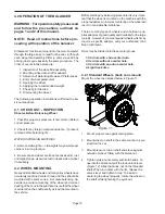
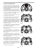
Before using the wheel balancer it is suggested that you
become familiar with the terminology and features of the
machine’s components. Refer to Figures 9 and 10 for
identification and location.
1.
Parameters - Rim Offse
t - Key is used to enter the
rim offset position using numbers from the distance
gauge.
Rim Diameter
- Enter the rim diameter.
Read the size stated on the tire sidewall.
Rim Width
- Press this key to enter the rim width. Use the rim
width calipers for measurement.
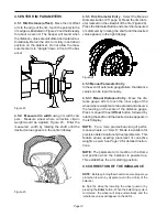
2.
Inside Weight Amount and Function Display Win-
dow
- Shows inside or left weight amount and vari-
ous operation messages.
3.
Position Indicator LEDs
- Displays the location for
wheel weight placement.
4.
Middle Display -
Used to display wheel parameters
or messages.
5.
Outside Weight Amount and Function Display
Window
Shows outside or right weight amount and
various operation messages.
6.
Function Button -
Used to activate the various func-
tions. Press this button followed by rotating the
shaft until the desired value appears in the display.
Press the “Enter” button to active the function.
7.
Weight Call-Back -
Pressing this key allows the
operator to recall the original weight imbalance value
and position to check for proper weight placement
in the event the check spin requires more weight
when in the clip - clip mode.
8.
Cancel
- Pressing this key interrupts any process.
9.
Enter
- This key activates whatever selection has
been requested, it also spins the wheel if guard frame
is down.
10. ALU-S and Spoke Mode -
Activates the ALU-S or
Spoke Mode. Each time this button is pressed pro-
gramming toggles between the two.
11. Mode Selection
- A series of placement locations
for custom weight location. Useful for the wide vari-
ety of custom wheels on today's market.
12. Weight Mode and Placement Display
- Displays
a pictorial reference of the chosen balance mode.
13. Multi-Operator Selection
- This key toggles be-
tween four operators designated as a, b, c, and d.
Wheel parameters are recalled upon command.
14. Fine Weight Toggle -
In normal mode
“FIN OFF”
round off is 0.25 oz or 5 gram, fine mode
“FIN ON”
round off is 0.05 oz. or 1 gram.
15. Oz/Gr -
Toggles between display values in Ounces
or Grams.
16. Display
- Easy to read, user friendly display featur-
ing large LEDs and one button functions.
17.
Weight Storage Tray
- Generous storage for a vari-
ety of weight profiles and sizes as well as built in
storage pockets for the standard centering cones.
18. Accessory Storage
- Four sturdy side mounted pegs
are supplied for storage of additional accessories.
19. Foot Operated Shaft Lock
- A foot operated shaft
lock is used to stabilize the shaft during the weight
placement process.
20. Shaft Adapter
- A common 40 mm size shaft is
used. The easily removable shaft can be replaced
for service or during use of certain wheel adapters.
21. Wheel Guard
- The standard wheel guard is a safety
feature for prevention of operator injury in the event
of loose weights, debris or wheel mounting failure.
The balancer is programed to spin upon guard clo-
sure as well as brake when the guard is raised.
22. Semi-Automatic Parameter Arm
- Both rim dis-
tance and rim diameters are automatically input with
the SAPE. The SAPE is also used in several proce-
dures for determining accurate rim profiles.
Summary of Contents for VPI SYSTEM II
Page 2: ......
Page 27: ...NOTES ...


