45
-
Ensure that the hydraulic system is clean and avoid dirt.
-
Fill the oil tank with 12 l hydraulic oil HLP 32 (JM No. 558.49.66).
-
Activate the lift and then press the “Up” button. Ensure that the lift raises, otherwise check the electric power
supply and correct polarity.
-
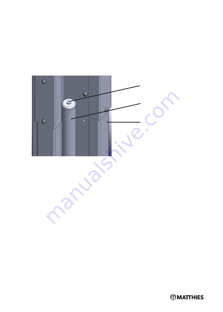
Lower the lift to the lowermost position. Now open the venting screws on both cylinders. Raise the lift by actu-
ating the “Up” button. Close the venting screws again if hydraulic oil emerges from them.
12.14. Commissioning
The non-recurring safety inspection must be conducted prior to commissioning (use the “Non-
recurring safety inspection” form).
Where installation of the lift is realised by a competent person (in-house trained installation fitter), he conducts the
safety inspection. If installation is realised by the operator, a competent person must be entrusted with the safety
inspection. The competent person confirms the faultless function of the lift on the installation protocol and the
non-recurring safety inspection form and releases the lift for use.
Following commissioning, the filled-in installation protocol must be sent to the Matthies
workshop service (fax 040 / 73 44 17 – 199).
First conduct a trial run of the lift in an unloaded state. Following a successful test and taking the “Non-recurring
safety inspection” form into consideration, a second test run should now be conducted in a loaded state.
Venting screw, Cylinder, Lift column
Vent screw
Cylinder
Lifting column
Summary of Contents for FOX 4000 H
Page 11: ...9 6 3 Data sheets a Standard version with 4090 mm ...
Page 12: ...10 b Lift column extension version with 4690 mm ...
Page 13: ...11 6 4 Load distribution ...
Page 14: ...12 6 5 Foundation plan ...
Page 15: ...13 6 6 Electrical diagram and parts list ...
Page 16: ...14 6 7 Hydraulic diagram and hydraulic parts list ...
Page 32: ...30 12 7 Installation of covers pipe clips and hydraulic line ...
Page 33: ...31 ...
Page 34: ...32 Ensure that hydraulic hoses F G and I are firmly connected and no leaks are evident ...
Page 37: ...35 12 10 Installation of limit switch ...
Page 41: ...39 B Safety catch A Cable from control cabinet B Safety catch cable ...
Page 42: ...40 C Shut off bar C Cable from control cabinet D Safety catch cable ...
Page 44: ...42 E Pump unit A Limit switch cable B Column extension cable bushing ...
Page 45: ...43 A Limit switch cable C Cable sleeve Clamp 102 Clamp 111 ...
Page 49: ...47 12 16 Dowel data sheet ...
Page 62: ...60 16 CE Confirmation ...


