


Jetter AG
Electrical connection | 6
JX3-THI2-RTD-EI User Manual
17 / 36
6 Electrical connection
NOTICE
Improving electromagnetic compatibility
The noise immunity of a system is determined by its weakest component. Cor-
rect connections, lines and shielding are key factors.
●
Ensure that the system is EMC-compliant.
●
Follow the instructions given in Application Note 016 on our homepage about
EMC-compatible installation of the electric cabinet.
NOTICE
Damages to material or functional impairment
Improper implementation of the wiring harness may cause mechanical stress.
●
Protect the cables from bending, twisting or chafing.
●
Install strain reliefs for the connecting cables.
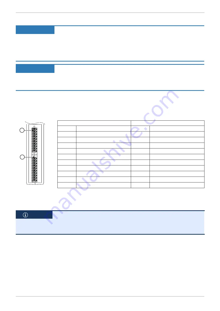
6.1 Temperature inputs X41, X42
The expansion module has two independent inputs for temperature measurement
with PT100/PT1000 sensors.
1
2
Position 1
Position 2
Pin
X41
Pin
X42
I1+
Current path to sensor 1+
I2+
Current path to sensor 2+
U1+
Voltage path to sensor 1+
U2+
Voltage path to sensor 2+
U1-
Voltage path to sensor 1-
U2-
Voltage path to sensor 2-
I1-
Current path to sensor 1-
I2-
Current path to sensor 2-
0V
Ground
0V
Ground
BR1
Not assigned
BR3
Not assigned
BR2
Not assigned
BR4
Not assigned
0V
Ground
0V
Ground
SHLD
Shielding terminal
SHLD
Shielding terminal
SHLD
Shielding terminal
SHLD
Shielding terminal
6.2 Connecting thermal sensors
The connection of thermal sensors is identical for both inputs.
INFO
To reduce interferences during temperature measurement, snap a split ferrite
core around the sensor cable and a ferrite core around each connection cable
within the sensor cable (e.g. by Würth Elektronik, part # 74271222). Attach the
snap-on ferrite core as close as possible to the terminal.
ü
The system is de-energized.
ü
A shielded cable is used.
1.
Bridge the connections on the module according to the connection type men-
tioned in chapter
Connection types of temperature sensors [
. Make sure
there is a low-resistance connection and a low contact resistance at the
bridges.
2.
Connect the cable of the thermal sensor to the module.