


9629 Microprocessor Controller
- 58 -
A
Adjustment knob .........................14
Anytime Messages ......................19
Applications ................................12
C
Calibration ...................................36
Calibration Mode .................. 11, 56
Closed Loop Mode ......................22
Connections .................................12
Controls .......................................14
D
Description ..................................13
Display ........................................23
Display Screens - Upper Line .....15
Down Touch Pad .........................14
During Weld Messages ...............19
E
Electrical Diagrams & Charts .....48
Electrical Installation ..................29
Emergency Stop ..........................19
Emergency Stop Push-button ......14
Enclosure (Main) ........................40
Enclosure (Door) .........................42
F
Forward Jog Speed ......................20
H
High Limit ............................17, 23
High Output ................................23
High Pulse ...................................21
Hour Meter ..................................26
I
Information Screens .....................57
Initial Calibration ........................36
Input Power .................................29
Interconnection Diagram ............53
Interconnections ..........................32
Introduction ................................. 11
Isolation Board, 9600-11R ..........46
J
Jog Forward ................................17
Jog Reverse .................................18
Jogging Disabled .........................18
L
Loop Sensing ..............................22
Low Limit ............................17, 24
Low Output .................................24
Low Pulse ....................................22
Low Speed ..................................21
M
Maintained Forward ....................18
Maintained Jog ............................14
Maintained Reverse ....................18
Maintenance ................................36
Mechanical Installation ...............28
Microcontroller Board, 9600-10 .44
O
Operating Mode ..........................54
Operational Sequence .................27
Operator Mode ..................... 11, 15
Output Connections ....................29
P
Parts List .....................................39
PCB Descriptions ........................44
Power Switch ..............................14
Pre-weld Messages ......................17
Pulsed Wire Feed ........................21
Q
Quick Start Manual ....................... 11
R
Ramp Time ..................................16
Rapid Jog ....................................14
Rapid Jog Forward ......................18
Rapid Jog Reverse .......................18
Rapid Speed ................................20
Remote High Input ......................25
Remote Low Input ......................26
Remote Start Enabled .................19
Retract Speed ..............................20
Reverse Jog Speed ......................20
S
S1 Connector ........................29, 49
S2 Connector ........................30, 50
S3 Connector ........................31, 51
Sensing Delay ......................19, 23
Set Speed .....................................25
Setup Mode ................... 11, 20, 55
Specifications ..............................12
Speed Adjustment Locked ..........17
Start Delay ...........................15, 19
Start Push-button .........................14
Stop Delay ............................16, 19
Stop Push-button .........................14
T
Tach High Input ..........................24
Tach Low Input ...........................25
Touch-up Calibration ..................36
U
Units ............................................26
Up Touch Pad ..............................14
W
Welcome Screen ..........................15
Wire Pulsing ................................21
Wire Retract .........................16, 19
Wire Speed ..................................15
Wire Speed (Locked) ..................17
Index
Summary of Contents for 9600 Series
Page 2: ...9629 Microprocessor Controller 2...
Page 6: ...9629 Microprocessor Controller 6...
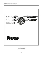
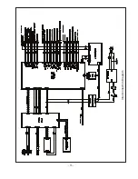
Page 41: ...9629 Microprocessor Controller 41 Figure 1 Enclosure SUB PANEL GROUND MAIN GROUND...
Page 43: ...9629 Microprocessor Controller 43 Figure 2 Enclosure Door...
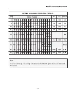
Page 49: ...9629 Microprocessor Controller 49 S1 CONNECTOR...
Page 50: ...9629 Microprocessor Controller 50 S2 CONNECTOR...
Page 51: ...9629 Microprocessor Controller 51 S3 CONNECTOR...
Page 52: ...9629 Microprocessor Controller 52...
Page 53: ...9629 Microprocessor Controller 53 Interconnection Diagram...


