


9629 Microprocessor Controller
- 29 -
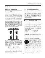
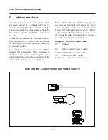
A. Input Power
The 9629 control is designed to operate on either
115VAC or 230VAC and is fitted with a 10 amp
fuse which is suitable for either voltage. The
unit will have been configured for your choice
of voltage prior to shipment. If it is necessary
to change the input voltage, this can be done as
follows:
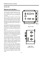
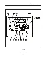
Open the front door of the unit and locate the
motor control module (See Figure 1, Page 41 for
the internal layout of the control). At the top, left
hand side of the module there are two jumpers,
these are marked J1A and J1B. These should
be set as shown in the diagram below.
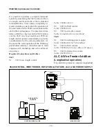
If supplied for 115VAC, the unit will be fitted
with a 6 ft. (2 m) long power cord with a suit-
able plug for this voltage. This plug must be
cut from the cable if the unit is to be used for
230VAC operation. The wires should be con-
nected as follows:
Brown
Live connection
Blue
Neutral connection
Green/Yellow
Ground connection
If it is necessary to remove and replace the power
cord, care should be taken to make the correct
connections to the 9629 control.
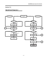
Section IX.
Electrical Installation
115V
230V
J1A
230V
115V
J1B
115V
230V
J1A
230V
115V
J1B
115VAC
230VAC
B. Output Connections
All output connections to and from the 9629
control are made by Amphenol connectors.
There are three Amphenol connectors, the lower
one is marked S1, the center one is S2 and the
upper one is S3. Interconnection of the 9629
control with associated equipment is shown on
the following pages.
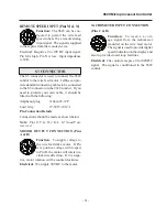
S1 CONNECTOR
The S1 connector is used to connect the 9629
control to an arc length control (if one is being
used in the system). Jetline can provide stan-
dard connecting cables to be connected to the
S1 connector on the 9629 control. If you need
to provide your own cable, it should be fitted
with the following:
Amphenol plug
3106A-20-27S
Cord Grip
97-3057-1012-1
Pin Connection Details
Connections should be made as shown below.
Note
:
Pins A, B, C, D, G, H, I, J, M and N are
unused.
PULSE LOCKOUT INPUT (Pins E & F)
(Alternative connection - see S2, pins E & F and interconnection diagrams)
Function
: When the control is
connected to a power supply with
pulsed current facilities, it is some-
times desirable to synchronize arc
length control with the current pulsing. When
the 9629 control is connected to the current
background signal through these connections,
it will allow a signal to be passed to the arc
length control.
Electrical
: You can connect a dry relay contact
or an open collector signal, Pin E is high, Pin F is
low. Either one must handle12VDC at 4mA.
Summary of Contents for 9600 Series
Page 2: ...9629 Microprocessor Controller 2...
Page 6: ...9629 Microprocessor Controller 6...
Page 41: ...9629 Microprocessor Controller 41 Figure 1 Enclosure SUB PANEL GROUND MAIN GROUND...
Page 43: ...9629 Microprocessor Controller 43 Figure 2 Enclosure Door...
Page 49: ...9629 Microprocessor Controller 49 S1 CONNECTOR...
Page 50: ...9629 Microprocessor Controller 50 S2 CONNECTOR...
Page 51: ...9629 Microprocessor Controller 51 S3 CONNECTOR...
Page 52: ...9629 Microprocessor Controller 52...
Page 53: ...9629 Microprocessor Controller 53 Interconnection Diagram...


