


9629 Microprocessor Controller
- 5 -
Table of Contents
Section I
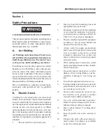
Safety Precautions .............................................................................................................7
A. Arc Welding ..........................................................................................................7
B. Electric Shock .......................................................................................................7
C. Arc Rays ................................................................................................................8
D. Fumes and gases ...................................................................................................8
E. Cylinders ...............................................................................................................8
F. Welding .................................................................................................................9
G. Moving Parts .........................................................................................................9
H. EMF Information ..................................................................................................9
I. Principal Safety Standards ..................................................................................10
Section II Introduction .....................................................................................................................11
Section III Specifications ..................................................................................................................12
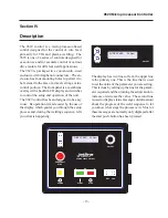
Section IV Description ......................................................................................................................13
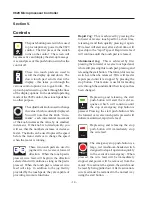
Section V Controls ...........................................................................................................................14
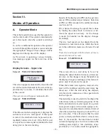
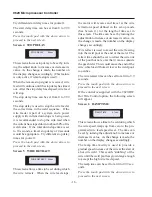
Section VI Modes of Operation ........................................................................................................15
A. Operator Mode ....................................................................................................15
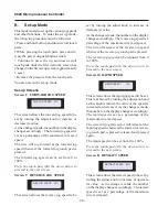
B. Set-up Mode ........................................................................................................20
C. Calibration Mode ................................................................................................22
Section VII Operational Sequence .....................................................................................................27
Section VIII Mechanical Installation ...................................................................................................28
Section IX Electrical Installation ......................................................................................................29
A. Input Power .........................................................................................................29
B. Output Connections ............................................................................................29
C. Interconnections ..................................................................................................32
Section X Maintenance ....................................................................................................................36
A. Calibration ...........................................................................................................36
B. Regular Maintenance ..........................................................................................38
Section XI Parts List .........................................................................................................................39
Section XII PCB Descriptions ............................................................................................................44
Section XIII Electrical Diagrams .........................................................................................................48
Index ...............................................................................................................................58
Summary of Contents for 9600 Series
Page 2: ...9629 Microprocessor Controller 2...
Page 6: ...9629 Microprocessor Controller 6...
Page 41: ...9629 Microprocessor Controller 41 Figure 1 Enclosure SUB PANEL GROUND MAIN GROUND...
Page 43: ...9629 Microprocessor Controller 43 Figure 2 Enclosure Door...
Page 49: ...9629 Microprocessor Controller 49 S1 CONNECTOR...
Page 50: ...9629 Microprocessor Controller 50 S2 CONNECTOR...
Page 51: ...9629 Microprocessor Controller 51 S3 CONNECTOR...
Page 52: ...9629 Microprocessor Controller 52...
Page 53: ...9629 Microprocessor Controller 53 Interconnection Diagram...


