


18 HomeRunner RBI User Manual – Rev 1.03a
Insteon Configuration
Unlike X-10 devices, each Insteon device comes factory preset with an address I.D. that cannot be
changed. The six-digit address is printed on a sticker on every Insteon device
. It is recommended
that you keep a list of all your Insteon devices’ addresses and their locations for reference. You
can write down each address as you unpack each device or save/print your Insteon
Configuration Device List and Scene List after you have installed them all.
First make sure the Insteon Power Line Modem (PLM) is connected to the
H
ome
R
unner
RBI’s
“PLM” jack using the provided network cable and that the green and yellow LEDs are on steady.
To access the
Insteon Configuration
window, click the
Define – Insteon
button on the toolbar (or
press
Ctrl+I
), or from within the Event Editor click
“Define”
then
“Configure Insteon.”
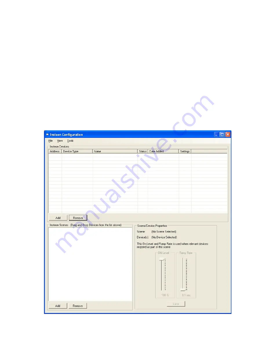
Here is
where you install and label all your Insteon devices, create Insteon lighting scenes and link
controllers with responders. The
“Insteon Devices”
section at the top is for adding, removing or
replacing your Insteon devices. The
“Insteon Scenes”
section at the bottom is for adding, removing
or editing Insteon scenes and device links.