


www.javad.com
www.javad.com
55
54
Stake
Real-Time Position Shift
Stake Sequence
Screen
The suggested
User Defined Button
options for new users
are displayed in the follow two screenshots.
Stake Action
Screen
When near the target point being staked tap
Start
to begin
collecting data and to average the displayed offset values.
When staking a point in a multipath environment, this is
an essential step that must be used with
RTK Verification
to
ensure the RTK initiation is correct. Choose
Accept
to store
the staked coordinate or
Reject
to discard them or to adjust
the position and try again.
Stake Action Expanded
Screen
The
CTT
(Course to Target)
Arrow User Defined Button
option
in the top left box displays the direction to the point
being staked while the distance to it is displayed in the
DTT
(Distance to Target) whitebox below it. Further down
are the
Ahead/Back
and
Right/Left
boxes that display the
distances to the point relative to the TRIUMPH-LS. The
Cut/
Fill
option is in the lower right box.
On the right side, the
Target Name
option is used as another
method to select the point being staked. When it is added
as a whitebox you must choose whether to “Key-in target
point name” or “Select target point from list”. Select the
option you prefer. Below it are
Point Description
,
Accept As
and
Verify Statistics
whitebox options.
The
Accept
As
whitebox is useful if you wish to store the
staked coordinate of a design point as new point rather
than having it stored in the design point’s record. After
collecting the staked design point press
Accept As
rather
than
Accept
if you desire to store it as a new point.
Real-Time Position Shift
Real-Time Position Shift
, allows real-time corrections to be
applied to receive base station corrections. A base station
can be started with an autonomous position and then
corrected by surveying a point with known coordinates.
The known point could be a point previously surveyed with
a base station setup in a different location. This feature is
useful for several scenarios:
You need to move or “leapfrog” your base station to extend the radio
range into a new area.
Your original base station point has been lost.
You wish to save time by starting the base station with it mounted to
the top of your vehicle. Setting the base station and radio up on the
top of vehicle by mounting it a roof rack or using a magnet mount saves
time by eliminating the need to setup tripods and can help protect the
base station from disturbances or theft in undesirable locations. For the
best performance, the base station should be mounted in a near level
position so that phase center variations and antenna offsets are correctly
applied. If you are parked on a sloped surface, a swivel mount can be
used to level the receiver on the top of your vehicle. Your vehicle should
be parked on solid ground where it will not move or sink.
The
Real-time Position Shift
function can be accessed from
the Advanced Setup menu (press the
Set Up
hardware
button twice >
Real-time Position Shift
). In this screen,
select a point you have collected RTK coordinates from
with an autonomous base station and then the known
coordinates of this point. Check the
Apply Shift
and the shift
will be applied to all the RTK surveyed points found in the
current project collected from this base station. This shift
will continue to be applied to all the points surveyed from
this base station.
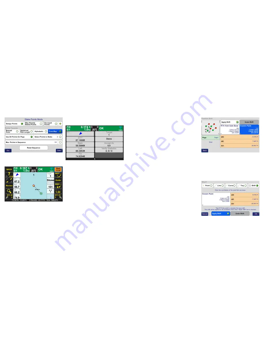
Position Shift
Screen
Real-time Position Shift
can also be accessed from the Collect
Action screen by clicking the button below the Start button
and changing the collection mode to Shift. In this mode
select the
Known Point
and then press
Start
from the action
screen to collect a point so that the offset can be calculated.
After it has been calculated you will be prompted to apply
the shift.
Position Shift
Screen from the Collect Action Screen


