


www.javad.com
www.javad.com
69
68
CoGo
CoGo
Shift
CoGo Shift
CoGo Shift
and
Rotate
are useful for shifting and rotating
design points to desired geodetic surveyed locations.
Upon opening the
Shift
,
Move
or
Rotate
functions you will
be prompted two options: to
Create New Points
or
Move
Existing Points
. The
Create New Points
would need to be
chosen if the desire is to shift surveyed points. Surveyed
coordinates are blocked as options to be shifted is the
Move
Existing Points
option is selected. The
Create New Points
would typically only be desirable and applicable to use if
some object needs to be physically relocated in the field
and the new location needs to be calculated. To adjust
surveyed coordinates from an autonomous base,
Real-Time
Position Shift,
DPOS
or
M-Shift
should be used.
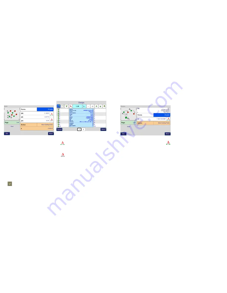
The
Multi-Select
screen is used to select the points to be
shifted. To select individual points in this screen, use
the
(
Check Hardware
) button for easier selection of
individual points.
Multi-Select
Screen - Selecting points 1 through 20, notice
the filter used to filter the list to points 1 through 20, the
select all button then is used to select all points
The
(
Delta
) button can be used to calculate the delta
between two points, from the first selected point to the
second selected point.
The
(
Delta DPOS
) button is used to recall the
DPOS
shift from a base station session. Use this feature to shift
design points. (Automatic shifting of design points created
from CoGo functions is planned to be implemented in a
future version of J-Field.)
Tap the
Move
button once ready to shift the selected points.
Rotate
CoGo Rotate
CoGo Rotate
is very similar to
CoGo Shift
. Here the
(
Delta
) button calculates the angle between the first
selected points to the second selected point with the
selected
PB
coordinate as the vertex.